


Storage
2007 HUV 4421 Gasoline and Diesel Vehicle Owner’s Manual Page 27
PREPARING THE VEHICLE FOR EXTENDED STORAGE
1. Unload the vehicle so that the tires are supporting only the weight of the vehicle.
2. Store the vehicle in a cool, dry place. This will minimize battery self-discharge. If the battery appears to
be weak, have it charged by a trained technician. Use an automotive-type 12-volt battery charger rated
at 10 amps or less. Check electrolyte level after charging and add distilled water if necessary. If the bat-
tery is dead, see Using A Booster Battery (Jump Starting) on page 46.
3. Make sure the key switch is in the OFF position and the Forward/Reverse handle is in the NEUTRAL
position. Chock the wheels.
Gasoline vehicles:
4. Prepare the fuel tank.
4.1. Fill the tank with fresh fuel.
4.2. Following the manufacturer’s directions, add a commercially available fuel stabilizer (such as Sta-
Bil
®
). Run the engine in a well-ventilated area to allow treated fuel to replace untreated fuel in the
carburetor.
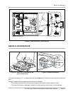
4.3. Disconnect the fuel vent line from the fuel tank vent nipple (Figure 35, Page 43).
4.4. Plug the fuel tank vent nipple so that it is air tight. Husqvarna recommends using a slip-on vinyl cap.
5. Remove both spark plugs, and pour 1/2 ounce (14.2 mL) of SAE 10 weight oil through each of the two
spark plug holes. Rotate the engine crankshaft by hand several times, then install both spark plugs.
Diesel vehicles: If Biodiesel fuel is used, see Biodiesel Fuel (Diesel Vehicles Only) on page 43.
6. Prepare the fuel tank.
6.1. Fill the fuel tank with fresh fuel.
6.2. Disconnect the fuel vent line from the fuel tank vent nipple (Figure 36, Page 43).
6.3. Plug the fuel tank vent nipple so that it is air tight. Husqvarna recommends using a slip-on vinyl cap.
All vehicles:
7. Change engine oil. See Engine Oil and Filter Change on page 35.
8. Disconnect the battery cables, negative (–) cable first. See WARNING “To avoid unintentionally start-
ing...” on page 9.
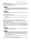
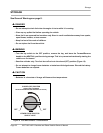
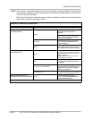
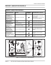
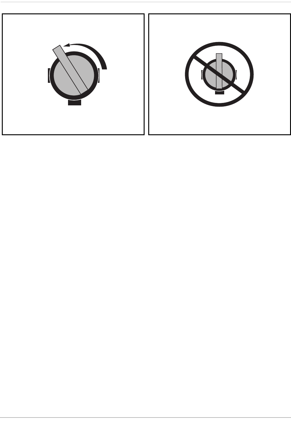
Figure 13 Fuel Shut-off Valve – Open Position Figure 14 Fuel Valve – Partially Closed Position
FULL OPEN (ON)
POSITION
VIEWED FROM SELECTOR
SIDE OF VALVE
VIEWED FROM SELECTOR
SIDE OF VALVE
PARTIALLY CLOSED
POSITION