


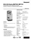

N20, N34 SERIES MN7220, MN7234
3 63-2587—1
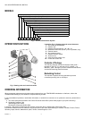
Rotary Movement
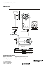
The control signal and the corresponding rotation direction
(clockwise or counterclockwise) can be selected using the
rotation direction switch (see part Rotation direction switch in
Fig. 2), thus eliminating the need to re-wire. To ensure tight
closing of the dampers, the actuator has a total rotation stroke
of 95°.
As soon as operating power is applied, the actuator may start
to run. When power is removed, the actuator remains in
position. For actuator-controller wiring instructions, see section
“Wiring” on page 5.
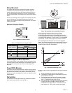
Rotation Direction Switch
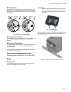
Fig. 3. Rotation Direction Switch
Feedback Signal and Manual Adjustment
If, while the actuator is not rotating, the user declutches it and
manually repositions the shaft adapter, the feedback signal will
then follow the new position at which the shaft adapter has
been left.
Power Off/On Behavior
In case the power to the actuator fails, after re-applying power,
the actuator acknowledges its present position and follows the
signal from the controller. This makes it unnecessary for the
actuator to employ autoadaption in order to re-map the control
signal settings.
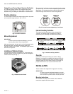
Dip Switches
The actuators are equipped with two dip switches accessible
after removing the access cover (see Fig. 4).
Fig. 4. Dip switches (view with PCB at bottom)
Autoadapt Dip Switch for Normal Operation
In its default shipping position, the autoadapt dip switch for
normal operation is set to ON as shown in Fig. 4. Dip switches
(view with PCB at bottom)4. If it is set to OFF, no autoadapting
is performed, and the control signal map remains constant.
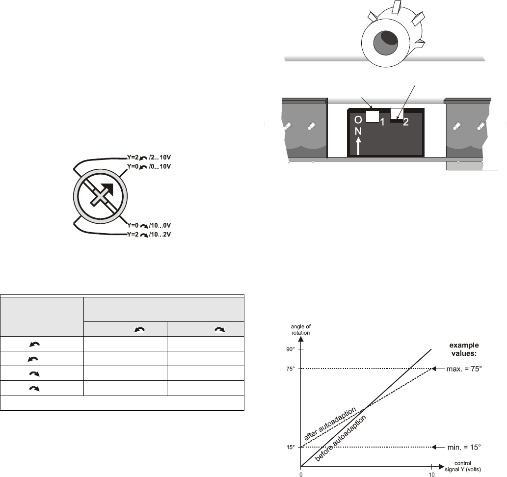
The autoadapt functionality does not have to be triggered.
Rather, the SmartAct actuator does this automatically when the
min. and max. control signals are provided (see Fig. 5); the
feedback signal is likewise autoadapted.
Fig. 5. Actuator positioning curve
In order to make use of the autoadapt functionality, proceed as
follows:
1. Set the autoadapt dip switch to the ON position.
2. If necessary, limit the stroke to the desired range using
the mechanical end limits.
3. Drive the actuator to the left end limit (totally counter-
clockwise) by setting the control signal as specified in
Table 1. Feedback/control signal values1.
4. Drive the actuator to the right end limit (totally clockwise)
by setting the control signal as specified in Table 1.
Feedback/control signal values1. The stroke has now
been limited to 0...100% of the control signal range.
Table 1. Feedback/control signal values
Rotation direction
switch position
Feedback/control signal when
actuator is
totally totally
Y=2 /2...10V U = 2 V U = 10 V
Y=0 /0...10V* U = 0 V U = 10 V
Y=0 /10...0V U = 10 V U = 0 V
Y=2 /10...2V U = 10 V U = 2 V
* Default shipping position.
autoadapt dip switch for
normal operation ( )
ON
voltage/current control signal
dip switch ( )
OFF