


SKU 68048, 6049, 6056 For technical questions, please call 1-800-444-3353 Page: 2
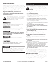
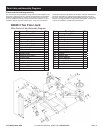
Jack Components
U-Joint (Not Shown)
Saddle
Handle
Handle Socket
Oil Fill Screw
(Not Shown)
Lifting Arm
Rear Caster
Fig. 1
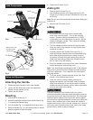
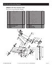
U-Joint
Hydraulic Unit
Fill Screw
Safety Valve Cover
DO NOT OPEN
OR ADJUST
Fig. 2
Setup and Operation
Attaching the Handle
1. Fasten the Upper Handle to the Lower Handle.
2. Loosen the Set Screw and insert the assembled
Handle into the Handle Socket.
3. Tighten the Set Screw.
Bleeding
1. L
oosen the Fill Screw (Fig. 2).
2. Insert the assembled Handle into the Handle Socket (Fig.
1) to operate the Release Valve.
3. Turn the Handle (Fig. 1) counterclockwise to open valve.
4. Pump the Handle (Fig. 1) up and down quickly for several
times to purge the air from the system.
5. Tighten the Fill Screw (Fig. 2).
Adding Oil
1. Remove the Fill Screw (Fig. 2).
2. Add qualied hydraulic oil of high grade into the Fill
Screw (Fig. 2) slowly until the oil reaches the top of the
oil ll hole.
Note: Do not touch the assembled Handle when adding the
hydraulic oil.
3. Replace the Fill Screw (Fig. 2)
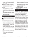
Lifting
1. Park vehicle on a at, level, solid, surface safely
away from oncoming trafc. Turn off the vehicle’s
engine. Place the vehicle’s transmission in “PARK”
(if automatic) or in its lowest gear (if manual). Set the
vehicle’s emergency brake. Then, chock the wheels
that are not being lifted.
2. Turn the Handle counterclockwise to lower the Jack.
Once the Jack is fully lowered, turn the Handle rmly
clockwise to close it.
3. Carefully position the Saddle of the Jack (Fig. 1)
under the vehicle manufacturer’s recommended lifting
point.(See vehicle manufacturer’s owner’s manual
for location of frame lifting point when lifting only one
wheel and frame lifting points when lifting the entire
front or rear end of the vehicle.)
4. Pump the Handle until the top of the Jack’s Saddle has
nearly reached the vehicle lifting point.
Note: The Jack should be positioned at 90° to the vehicle’s
lifting point to ensure the Jack’s Saddle and vehicle lifting
point are in alignment. If not, reposition the Jack before
lifting the vehicle.
5. To lift the vehicle, pump the Handle of the Jack. Use
smooth, full strokes for best results.
6. Once the vehicle is raised, slide a jack stand of
appropriate capacity (not included) under the proper
lifting point referred to in the vehicle owner’s manual.
Always use two jack stands, position them at the same
point on each side of the vehicle.
The rated capacity of jack stands is per pair, not the
individual capacities combined unless specically noted on
the product by the jack stand manufacturer. Do not exceed
rated jack stand capacity. Ensure that the vehicle support
points are fully captured between the outer lugs of both jack
stands. Use a matched pair of jack stands per vehicle to
support one end only. Use 1 pair per vehicle only. Failure to
do so may result in sudden loss of load, which may cause
personal injury and/or property damage.