


SKU 66183 For technical questions, please call 1-800-444-3353. Page 4
SPECIFICATIONS
Jack Capacity 7,000 Pounds
Maximum Lift 59-1/4”
Minimum Height 6”
UNPACKING
When unpacking, make sure that
the item is intact and undamaged. If any
parts are missing or broken, please call
Harbor Freight Tools at the number shown
on the cover of this manual as soon as
possible.
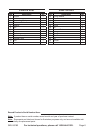
Note: For additional information regarding
the parts listed in the following pages,
refer to the Assembly Diagram near
the end of this manual.
OPERATING INSTRUCTIONS
Read the ENTIRE IMPORTANT
SAFETY INFORMATION
section at the beginning of this
manual including all text under
subheadings therein before set
up or use of this product.
Designate a work area that is clean 1.
and well-lit. The work area must not
allow access by children or pets to
prevent injury and distraction.
Use the Jack on solid, level surfaces, 2.
capable of supporting the weight of
the Jack, equipment being lifted, and
operator.
To increase stability, the Jack can be 3.
bolted to a thick board, metal plate,
or a cement surface. Use the three
mounting holes on the Base as a tem-
plate to mark the location where three
1/2” diameter holes will be drilled into
the surface. Drill and clean out the
three holes. Align the three mount-
ing holes with the three drilled holes
and secure the Jack to the oor using
masonry expansion anchors (not in-
cluded). Only use materials capable
of bearing the weight of the Jack and
load being lifted.
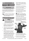
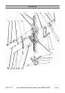
To raise loads, pull the Ratchet Con-4.
trol Lever (10) up until the mechanism
clicks and the Latch engages.
Place the jack’s lift nose completely 5.
under the object being lifted.
Slowly pump the handle to raise the 6.
load. Keep a rm grip on the handle
while operating the jack.
7. Caution! To avoid injury keep
hands away from the Lift Nose when
raising a load. Keep bystanders and
pets away when a load is raised. Do
not work under a raised load.
After the load is raised to the desired 8.
height, insert a grade 5, 1/2 inch bolt
(sold separately) through the hole in
the Lift Column (2) immediately below
the lifting mechanism.
Ratchet Control
Lever (10) in down
position.
Handle
Lift
Nose
Ratchet
Latch (11)
Insert additional supports to make 9.
sure the load is properly supported at
the lift point to prevent shifting.
To lower the load; move the Ratchet 10.
Control Lever to the down position,