


Part Number Quantity Description
12 1
3
/
3
/
3
8
-16 Spinlock Nut
13 2 Linkage Adjustment Pin
14 2
1
/
4
/4/
in. E-Ring
15 1 Drive Link
16 1 Stand Off Bracket
17 4
1
/
4
/4/
in.
-20 x
1
/
2
in. Thread Cutting Screw
18 1 Ball Bearing
19 1 221455A Crankarm
20 2 #10 Tek Screw
21 4
1
/
4
/4/
in.
-20 x
1
/
2
in.
Hex Bolt
Part Number Quantity Description
13 2 Linkage Adjustment Pin
15 1 Drive Link
16 1 Stand Off Bracket
18 1 Ball Bearing
19 1 221455A Crankarm
20 2 #10 Tek Screw
Part Number Quantity Description
12 1
13 2 Linkage Adjustment Pin
14 2
15 1 Drive Link
16 1 Stand Off Bracket
17 4
18 1 Ball Bearing
19 1 221455A Crankarm
20 2 #10 Tek Screw
21 4
Part Number Quantity Description
1 1 Actuator
2 1 Mounting Bracket
3 1 Mounting Plate
4 4
1
/
4
/4/
-20 x
1
/
2
in. Threadstud
5 4
1
/
4
/4/
-20 x
3
/
3
/
3
4
/4/
in. Threadcutting Screw
6 10
1
/
4
/4/
-20 Spinlock Nut
7 2
1
/
2
in. Crankarm
8 2
5
/
16
-18 x 1
1
/
2
in. Bolt
9 2
5
/
16
-18 Spinlock Nut
10 1 1 in. Crankarm
11 1
3
/
3
/
3
8
-16 x 2
1
/
2
in. Carriage Bolt
Part Number Quantity Description
1 1 Actuator
2 1 Mounting Bracket
3 1 Mounting Plate
10 1 1 in. Crankarm
Part Number Quantity Description
1 1 Actuator
2 1 Mounting Bracket
3 1 Mounting Plate
4 4
5 4
6 10
7 2
8 2
9 2
10 1 1 in. Crankarm
11 1
1
14
15
19
5
3
4
6
13
14
13
7
8
20
21
9
18
17
16
6
2
6
11
10
12
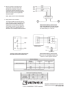
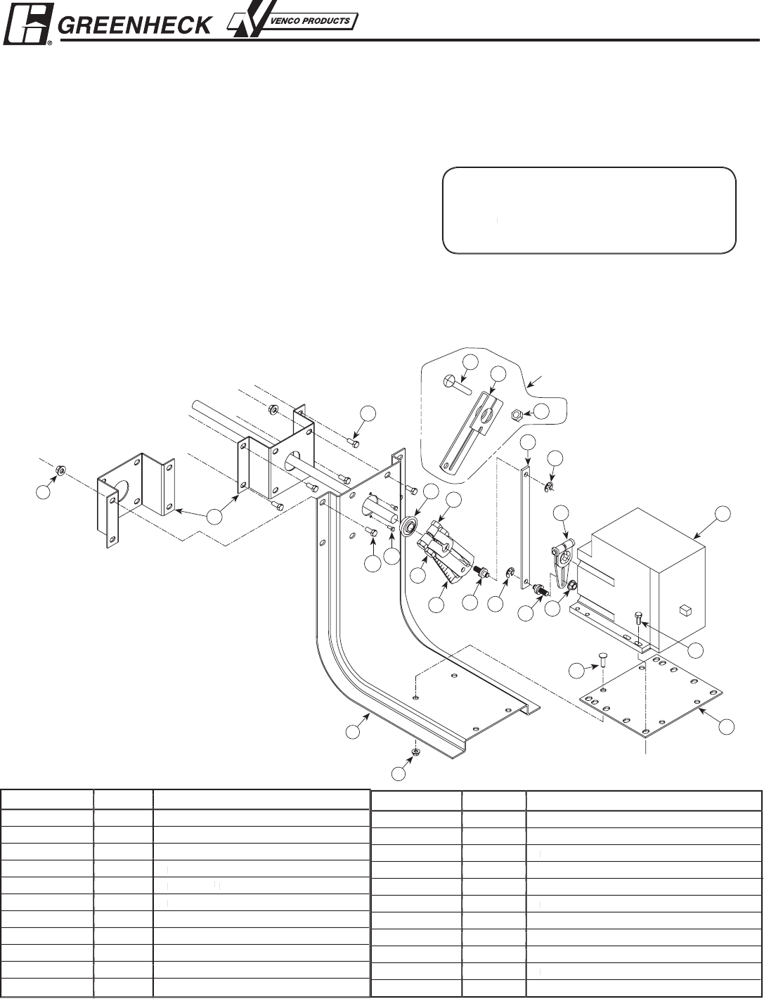
These parts are for
use with a 1 in. shaft
Tools Required:
Wrenches
:
(1
)
3
/
3
/
3
8
, (2
)
1
/
2
, (1)
9
/
16
, (1
)
7
/
16
, and (1)
5
/
16
(1) Hammer
P
art #454200
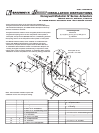
INSTALLATION INSTRUCTIONS
Honeywell Modutrol IV Series Actuators
Models M4182, M9185D, & M8182
UL Listed Electric Actuators with Two Position Control
These instructions apply to the external field installation of
Honeywell actuators on Greenheck model VCD Control Dampers,
FSD Fire/Smoke Dampers, and SMD Smoke Dampers when they
are duct mounted or sleeved.
Honeywell actuators rotate to their energized position when power
is applied and spring return to their fail position when power is
interrupted, except for the M9185D which is a modulating actuator
that spring returns to the fail position when power is interrupted
.
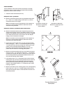
The M9185 model actuator, when installed on model FSD fire/
smoke and SMD smoke dampers in accordance with these
instructions, complies with the requirements of NFPA 90A and
UL Standards 555 and 555S. Smoke or Fire/Smoke dampers are
normally arranged to operate automatically in response to heat,
signals from a heat or smoke detector, or a building alarm system.
Installation must be acceptable to the authority having jurisdiction.
Note: These actuator models require fi eld
calibration for the zero and span setting.