


7
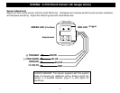
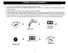
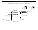
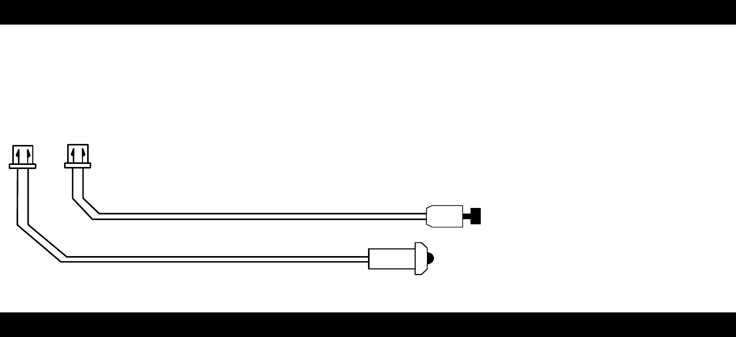
WIRING: 2-PIN LED / 2-PIN Program-Valet Button (26 gauge wires)
Mount Status LED in a visible location on the Dash or Console. Connect the small 2-pin plug from the LED to the
control module. Note: Connectors are designed so that they will only plug into their appropriate slots.
Mount the Valet/Program/Override button in a suitable location. Connect the 2-pin plug from the Switch to the
control module. Note: Connectors are designed so that they will only plug into their appropriate slots.
VALET / PROGRAM SWITCH
STATUS LED
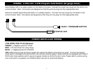
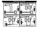
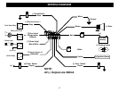
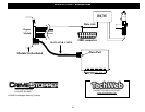
POWER DOOR LOCK WIRING
3 PIN DOOR LOCK PLUG (Optional):
GREEN: (-) Negative pulse for LOCK
RED: +12V Coil Power for using relays.
BLUE: (-) Negative pulse for UNLOCK
Hint: Determine the type of locking system the vehicle has before connecting any wires. Incorrect connection
could result in damage to the alarm and/or the vehicle’s locking system. Some vehicles are equipped with Class 2
DATA door locks systems which require a bypass module to control the door locks. Please refer to vehicle wiring
color chart which is supplied via TechWeb (basic service) for authorized dealers.