


2
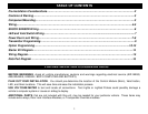
TABLE OF CONTENTS
Pre-Installation Considerations…..…….……………………………….……………………………………….……2
Cautions & Warning…………………………..……………...……………………..…………………….…….…..…..3
Component Mounting………………..………………………………………………………………………………….3
Wiring………………………………………………………………………..…………………..………….….…….….4-5
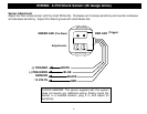
SHOCK SENSOR Wiring…….…………….………….….…..…………………………………………………………6
LED and Valet Switch Wiring………………..………………………….…….........................................................7
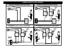
Power Door Lock Wiring……………………………………………………….………………………….…...….…7-8
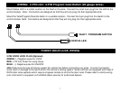
Transmitter Programming………………………………………………………………………………………………9
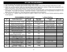
Option Programming…………………………………………….…….………………….…….…………...….…10-13
Starter Kill Diagram..……………………………………………..……………………………..……………..………14
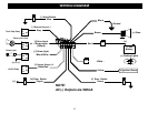
Wiring Diagram..…………………………………………………..……………………………..……………..………15
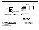
Data Port Diagram …………………………………………………………………………………………………..…16
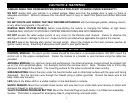
PR PRE-INSTALLATION CONSIDERATIONS
BEFORE BEGINNING, check all vehicle manufacturer cautions and warnings regarding electrical service (AIR BAGS,
ABS BRAKES, ENGINE / BODY COMPUTER AND BATTERY).
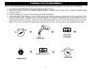
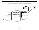
PLAN OUT YOUR INSTALLATION. You should pre-determine the location of the Control Module (Brain), Valet button,
LED, and Siren locations. This will save time and ease the installation process.
USE VOLT/OHM METER to test and locate all connections. Test Lights or Lighted Probes could possibly damage a
vehicle’s computer system or cause an airbag to deploy.
ADDITIONAL PARTS, that are not included with this unit, may be needed for your particular vehicle. These items may
include extra relays, Door Lock Interface Modules, or Transponder Override modules.