


©2005 Edelbrock Corporation
Rev. 2/05 - DC/mc
Brochure No. 63-0342
Catalog #8729
Edelbrock Corp., 2700 California St., Torrance, CA 90503
Tech Line: 1-800-416-8628; E-Mail: Edelbrock@Edelbrock.com
Edelbrock Fiber Laminate Spacer Kit #8729
for Edelbrock 5.0L Manifold #7123
INSTALLATION INSTRUCTION
Please study these instructions carefully before installing your new spacer kit. If you have any questions or problems, contact our
Technical Hotline at: 1-800-416-8628 from 7:00 am t- 5:00 pm, Monday-Friday, Pacific Standard Time or e-mail us at:
Edelbrock@Edelbrock.com. Please fill out and mail your warranty card.
Description: This kit includes a base to upper gasket for each side of the wood laminate spacer and the appropriate length bolts to
join the upper and lower manifolds. The spacer is 7/16” thick and the additional gasket is 3/64” thick for a total of approximately
1/2” thickness. The spacer provides the following benefits:
1) Raises the upper manifold 1/2” for increased valve cover clearance.
2) Provides heat insulation from lower to the upper manifolds.
3) Adds a small amount of runner length for torque increases.
CAUTION:
You must check your hood clearance before installation. Due to the 1/2”
additional height of the spacer, this spacer will not fit under the stock hood on
some vehicles. Hood clearance can be checked by forming cones with modeling
clay and placing them on various locations on your intake manifold. Close the
hood completely, open it, and measure the heights of the cones. You will need
1.0” clearance; 1/2” for the spacer and 1/2” to accommodate engine torque over
motion.
1. Disconnect battery negative (-) cable.
2. Disconnect necessary electrical connections, control cables,
linkages, vacuum hoses, ventilations hoses, and coolant hoses
at throttle body and manifold. Do not disconnect fuel lines
unless absolutely necessary. Special tools and
procedures are required to re-install fuel lines.
3. Remove upper intake manifold and gaskets.
4. Install upper-to-lower manifold gasket (dry), fiber laminate
spacer, another upper-to-lower manifold gasket, and upper
manifold using hardware supplied (see Figure 1 and
Fastener Location Chart). Upper manifold must be
positioned so that the throttle body is on the passenger’s side
of the vehicle, not the driver’s side.
NOTE: Do not overtighten the manifold to base
fasteners. Use a short box or open end wrench only.
5. To re-install the remaining components, reverse removal procedure. Adjust all
control cables. If automatic transmission equipped using an Edelbrock thottle
body, refer to the throttle body instructions for transmission T.V. (throttle valve)
cable linkage adjustment.
6. Connect battery negative (-) cable.
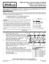
A
B
C
D E
F
GH
Figure 1 - Intake Manifold top-to-bottom faster locations
PERFORMER RPM II
Location Fastener
A 5/16” x 5” Bolt
B 5/16” x 2” Stud, Washer, Nut
C 5/16” x 2” Stud, Washer, Nut
D 5/16” x 2” Stud, Washer, Nut
E 5/16” x 2” Stud, Washer, Nut
F 5/16” x 2” Stud, Washer, Nut
G 5/16” x 7” Bolt, Washer
H 5/16” x 7” Bolt, Washer
Kit Contents
Qty. Description
❑ 1 Fiber Laminate Spacer
❑ 2 Base to Upper Gaskets
❑ 5 5/16” Hex Nuts
❑ 5 5/16” x 2” Studs
❑ 1 - 5/16” x 5” Bolts
❑ 2 - 5/16” x 7” Bolts
❑ 7 - 5/16” Split Lock Washers
INSTALLATION