


©2003 Edelbrock Corporation
Brochure No. 63-0079
Page 1 of 2
Rev. 1/03
ACCU-DRIVE CAM GEAR DRIVE SYSTEM
Catalog #7892 - Small-block Ford V8s, 289/302/351-W
Catalog #7893 - 1985 -1995 5.0L Ford V8s with Hydraulic Roller Lifter Cams
INSTALLATION INSTRUCTIONS
(4º retarded at the crank, 2º at the cam) and install on keyway onto
crankshaft. Use the “0º” standard keyway hole as a baseline for
camshaft timing.
(d) Install the one-piece Ford fuel pump drive #C3AZ-6287-B and
retaining capscrew. Finger tighten only at this time to hold parts in
place. Make sure pin is in pump drive.
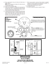
5. Align the cam gear and crank gear timing marks as shown in Figure 1.
6. Install the idler gear sub-assembly as follows:
(a) The large idler gear must be installed on the passenger side (right
side) of the engine.
(b) With large idler cranked tightly into mesh, make certain the small
idler (left side of engine) has free vertical movement (clearance) of
no less that .005" or no more than .070". NOTE: The gears will be
severely damaged from friction if they do not have the proper
running clearance as noted.
7. With the idler sub-assembly fully installed in mesh with crank and cam
gears and the large idler gear axle all the way back against the block,
check the clearance between end of idler axles and front cover as
follows:
Please study these instructions carefully before installing your new Accu-Drive Cam Drive System. If you have any questions or problems, do not
hesitate to contact our Technical Hotline at: (800) 416-8628 from 7:00 am to 5:00 pm, Monday through Friday, Pacific Standard Time or e-mail us
at: edelbrock@edelbrock.com. Please fill out and mail your warranty card.
• EMISSION CONTROL SYSTEMS: Check local laws for requirements. Not legal in California on pollution-controlled motor vehicles.
• POWER PACKAGE: Edelbrock Accu-Drive gear drives are part of a Total Power Package parts system that can be completed with the use of dyno-matched
Performer, Performer RPM, or Torker II cams,intake manifolds, and carburetors. For competition applications, use Edelbrock Victor intake manifolds. Please
refer to the Power Package Guide in the Edelbrock catalog to select all the components you need. To order a catalog, please call 1-800-FUN-TEAM.
• ACCU-DRIVE OPERATING PRINCIPLE
The Accu-Drive system utilizes a free floating idler gear that is self-aligning and connects the crankshaft and camshaft gears into proper mesh. The large
floating idler gear is positioned on the right side of the engine (passenger side). During normal operation, the drive power is
transmitted from the crankshaft through the large floating idler to the camshaft gear. During the running operation, there is no backlash between these
gears.
The small idler gear (located opposite the large idler gear driver side) is also free floating. This small gear does not carry any operating gear loading. The
small idler must be allowed to float vertically as noted in Figure 1. The small idler prevents the large idler gear from being
disengaged from mesh in the event the engine is rotated backwards.
• GEAR ASSEMBLY CAUTION NOTES:
❑ Never hammer directly on gears. You will damage the gear teeth and cause early failure.
❑ Lubricate all gears and bearings with engine oil before installing front cover.
❑ The small idler gear must be free to float vertically with the large idler gear in tight gear mesh with the crankshaft and camshaft gears. See Figure
1 for proper clearance. CAUTION: If gears do not have proper clearance, the gear teeth will become overheated and discolored and will fail due to
excessive friction between the mating gears.
❑ Large idler gear shaft length may require material removal to obtain the correct clearance between the cylinder block and front cover. See Figure 3.
❑ If a non-stock front cover is used, be sure idler gear axles do not have more than .030" front end clearance. Install allen head capscrews inside cover
(if necessary) to obtain proper clearance.
❑ Do not use aluminum hub harmonic balancer with your Accu-Drive. Use only stock or aftermarket steel harmonic balancers.
INSTALLATION INSTRUCTIONS
NOTE: THE FOLLOWING STEPS ARE CRITICAL FOR THE PROPER OPERATION OF YOUR ACCU-DRIVE!
1. Remove stock timing cover. Rotate engine to Top Dead Center of cylinder
#1 so that the timing marks on the original crank and cam sprockets are
directly lined up with each other, i.e. the mark on the crank sprocket will
be straight up and the mark on the cam sprocket will be straight down.
Using suitable gear puller, remove stock crank and camshaft sprockets
and timing chain. Refer to repair manual if necessary for individual steps.
2. Assemble Accu-Drive as shown in Figure 1.
3. Install crank gear with the large inside chamfer toward rear of engine and
timing mark toward front of engine. Make certain crankshaft drive key is
aligned with keyway of the crank gear before assembling.
4. See Figure 2 “Camshaft Gear Assembly” for correct assembly.
(a) Place well-lubricated thrust washer on the rear (block) side
of cam gear.
(b) The Edelbrock Accu-Drive system is furnished with an 0.032" thick
thrust ring that installs between the back side of the cam gear and
the front side of the camshaft thrust plate. Torque the thrust plate
retaining capscrews to 9-12 ft./lbs. NOTE: No thrust button is used
on Ford engines.
(c) Select the desired keyway in the crank gear “0”
(standard), “A” (4º advanced at the crank, 2º at the cam), or “R”