


PERFORMER RPM
Camshaft/Lifters/Lube Kit
CATALOG #7122
MODEL: 289-302 c.i.d. Ford V8 (not for
Boss 302 or 1985 & later roller lifter engines)
TO AVOID THESE PROBLEMS YOU MUST DO THE
FOLLOWING:
Carefully study and understand all instructions.
Examine the camshaft for possible shipping damage (if
damaged contact you dealer immediately).
PREPARATION CHECKLIST
• TOOLS AND EQUIPMENT
Use the following checklist for items needed.
box and open-end wrenches
socket set
distributor wrench
pliers (channel locks & hose clamp)
screw drivers (regular and phillips)
torque wrench
hammer
gasket scraper or putty knife
timing light
vacuum gauge
rags
water bucket
harmonic balancer puller
gear puller- for crankshaft sprocket
HARDWARE & PARTS TO BUY
gaskets- Fel-Pro #1250, OEM or equivalent
pipe plugs, if needed
Edelbrock Gasgacinch, #9300
RTV Silicone Gasket Sealer
chalk
paper and pencil
radiator coolant
teflon tape
Edelbrock Performer-Link True Rolling Timing Chain and Gear
Set #7811/#7820 or Accu-Drive Gear Drive #7892
Edelbrock Sure Seat Valve Springs, #5722
Manifold bolt kit #8524
• INSTRUCTIONS FOR ENGINE PARTS REMOVAL BEFORE CAMSHAFT INSTALLATION
1. Disconnect battery.
2. For ease of installation, keep all parts in some sort of order.
WARNING: Do not remove radiator cap or radiator hose if
engine is hot.
3. Drain radiator coolant, move fan shroud back and remove fan
and spacer from water pump. On air conditioned vehicles,
remove bolt, lower idler pulley and compressor-to- water pump
mount. Disconnect hoses and brackets. Most vehicles will
require radiator removal prior to cam removal. Remove water
pump.
4. Disconnect all linkage from carburetor such as throttle, throttle
springs, transmission, cruise control and automatic choke.
5. Tag and remove vacuum lines.
6. Remove valve covers.
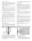
7. Remove distributor cap and wires, rotate engine until rotor
points towards number 1 terminal in cap and pointer on front
cover is on Top Dead Center (TDC) and remove distributor.
Note the approximate position of the vacuum advance canister
in relation to the manifold to assist in getting the distributor
properly located during re-installation.
©1997 Edelbrock Corp. Rev.1/97
• PLEASE study these instructions carefully before installing
your new camshaft. If you have any questions or problems, do
not hesitate to call our Technical Hotline at: 1-800-416-8628.
• CAMSHAFT: Edelbrock Performer RPM camshafts are ground
specifically for use with the corresponding Performer RPM
manifold. The Performer RPM manifold #7121, and Performer
RPM camshaft #7122, are designed to work as a team to give
you better driveability and performance. They are dyno-matched
and street-proven. For best results, use the Edelbrock
manifold/camshaft package with the carburetor and headers we
recommend. The Performer RPM camshafts are designed for use
with modified or high performance cylinder heads and valve
train components only. Screw-in studs and H.P. adjustable rock-
er arms must be used.
NOTE: Maximum performance is achieved only when the
Edelbrock Performer RPM Power Package components are used
with the following equipment:
• Performer RPM manifold/camshaft/timing set/valve springs
• Performer Series carb #1405 (600 cfm) or #1407 (750 cfm)
• fuel delivery system of sufficient capacity
• 1-3/4" headers
• aftermarket/re-curved distributors
• IMPORTANT: This instruction sheet provides general installa-
tion guidelines which can affect your warranty. Read it carefully.
It is not our intent to cover each detail of installation here; a
step-by-step procedure manual would be far too lengthy. We
want to caution you that installing a camshaft is a complicated
procedure that requires a good general knowledge of automotive
engines. If you are not confident that you can complete the
camshaft installation successfully, we suggest you consider hav-
ing it installed by an experienced mechanic.
CAUTION: Improper installation will result in LOW
MILEAGE, POOR PERFORMANCE, COSTLY REIN-
STALLATION, and ENGINE DAMAGE.
page 1