


©2004 Edelbrock Corporation
Rev. 1/04 - RS/mc
Catalog #15008
Brochure #63-0248
Page 1 of 2
BLOW OFF VALVE
Catalog # 15008
INSTALLATION INSTRUCTIONS
®
PLEASE study these instructions carefully before installing your new Edelbrock Blow Off Valve. If you have any questions or
problems, do not hesitate to contact our Technical Hotline at: 1-800-416-8628, from 7am-5pm, Monday-Friday, Pacific
Standard Time or via e-mail at: Edelbrock@Edelbrock.com
. Please fill out and mail your warranty card.
Installation Procedure
KIT CONTENTS
Qty
. Description
❑ 1 Blow-Off Valve
❑ 1 O-Ring
❑ 1 V-Band Mounting Clamp
❑ 1 Steel Mounting Flange
❑ 1 Aluminum Mounting Flange
❑ 1 10mm Hose Banjo Fitting
❑ 1 Hose Fitting Banjo Bolt
❑ 2 Hose Fitting Sealing Washers
• Description: This blow off valve is designed to allow boost pressure to be bled from the intake piping on throttle off, while
in boost. Bleeding off boost pressure keeps turbocharger speed up during shifts which reduces turbo boost lag. This also
protects the turbo from surging when the throttle is closed suddenly.
•
NOTE: This kit requires cutting and welding. If you are not experienced with fabrication and welding, you should have
this installation performed by a professional.
1. The blow-off valve should be located between the turbo
compressor outlet, and the throttle body.
2. Select either the steel or aluminum mounting flange,
depending on whether your intake plumbing is steel or
aluminum. Mark the area where the flange will be
attached, cut the piping to accept the flange, and weld
the flange to the piping. After welding the mounting
flange to your compressor plumbing, and allowing the
materials to cool sufficiently, you may attach the blow-
off valve to the mounting flange using the supplied v-
band clamp and o-ring.
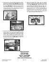
3. The easiest way to attach the blow off valve is to
remove the allen bolt and threaded sleeves from the v-
band clamp
(See Fig. 1)
. You will then be able to
stretch the v-band clamp over the flange. Allow the
clamp to slip completely over the flange
(See Fig. 2)
.
Fig. 1
Fig. 2