


®
FORD FLATHEAD CYLINDER HEADS
For 1949-53 Ford/Mercury 24-Stud V8s: Catalog #1115
For 1948-Earlier Ford/Mercury 24-Stud V8s: Catalog #1125
INSTALLATION INSTRUCTIONS
PLEASE study these instructions carefully before beginning this installation. Most installations can be accomplished with common tools and
procedures. However, you should be familiar with and comfortable working on your vehicle. If you do not feel comfortable performing this
installation, it is recommended to have the installation completed by a qualified mechanic. If you have any questions, please call our Technical
Hotline at: 1-800-416-8628, 7:00 am - 5:00 pm, Pacific Standard Time, Monday through Friday or e-mail us at Edelbrock@Edelbrock.com.
IMPORTANT NOTE: Proper installation is the responsibility of the installer. Improper installation
will void your warranty and may result in poor performance and engine or vehicle damage.
PLEASE complete and mail your warranty card. Be sure to write the model number of this product in the "Part #____" space. THANK YOU.
• INSTALLATION: Installation is the same as for stock, except for torque values and sealants. Please note specifications below:
NOTE: It is the customer’s responsibility to check valve to cylinder head clearance prior to final assembly. Failure to do so
could result in serious engine damage.
• HEAD GASKETS:
For #1115: Use Fel-Pro #1055 (right) and #1056 (left) copper sandwich gaskets.
For #1125: Use Fel-Pro #HS 7548 B (copper, 3 large irregular water holes on centerline), Fel-Pro #HS 7283 (copper, 2 small round water holes
on centerline), or Victor #3036 (copper).
Those who require a water bypass must drill the deck using their gasket as a template. A 1/4” diameter hole should be adequate.
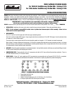
Refer to Figure 1 for torque sequence and torque specs. A re-torque is necessary after engine warm-up and complete cool-down. A re-torque
after each of three (3) hot-cold cycles is recommended for normally aspirated engines, and a re-torque after each of five (5) hot-cold cycles
is recommended for forced induction (blown) applications.
• SEALANTS: Follow the gasket manufacturer’s recommended sealant. Use liquid teflon sealant or teflon tape on pipe thread fittings in heads.
This will prevent thread galling and stripping upon removal.
• COMPRESSION RATIO: These heads will yield an 8:1 compression ratio with a 3/16" base relief and the stock bore and stroke. There is a
3/10 ratio increase for every 1/8" increase in stroke.
• SPARK PLUGS: A 14mm, 3/4” reach, gasket seat, 5/8” hex sparkplug is recommended, such as Champion RC12YC, RC14YC, or equivalent.
Heat range will vary with different combinations and conditions. Use anti-seize on spark plug threads to prevent thread galling!
FIGURE 1 - CYLINDER HEAD FASTENER TORQUE SEQUENCE
• Torque Studs to 50-55 ft./lbs.
• Torque Bolts to 60 ft./lbs.
• Torque in at least 3 steps such as 30, 40, 50 ft./lbs. or 30, 45, 60 ft./lbs.
• Re-torque required after initial warm-up and cool-down
Edelbrock Corporation • 2700 California St. • Torrance, CA 90503
Tech Line: 800-416-8628 • E-Mail: Edelbrock@Edelbrock.com
Catalog #1115, #1125
Rev. 2/06 - RS/mc
©2006 Edelbrock Corporation
Brochure #63-0351