


03-TM-0037 REV 13
Page 4 of 24
6.6. BATTERY REPLACEMENT AND TESTING.............................................................. 18
6.7. BEACON OFF-CURRENT TEST................................................................................ 21
6.8. BATTERY DISPOSAL. ............................................................................................... 21
6.9. BEACON STORAGE. ................................................................................................. 21
6.10. BEACON OVERHAUL.............................................................................................. 21
SECTION VII ............................................................................................................ 22
WARRANTY DK100/DK120/DK130/DK140 ........................................................ 22
SECTION VIII........................................................................................................... 23
SERVICE PROGRAM DK100/DK120/DK130/DK140......................................... 23
8.1. BEACON RETURN – DEFECTIVE............................................................................. 23
8.2. BEACON RETURN - NO DEFECT. ............................................................................ 23
8.3. BEACON RETURN - OUT OF WARRANTY. ............................................................. 23
8.4. BATTERY CHANGE/OVERHAUL FOR THE DK100 & DK130. ................................ 23
SECTION IX .............................................................................................................. 24
PROCEDURE FOR RETURNING DK SERIES BEACON TO FACTORY ..... 24
9.1. BEACON SERVICE. ................................................................................................... 24
9.2. BATTERY CHANGE/OVERHAUL.............................................................................. 24
TABLE OF FIGURES
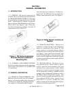
Figure 1. DK Series Underwater Acoustic Beacon Installed in Mounting Kits ............. 5
Figure 2. Water Switch Location on Beacon.................................................................... 5
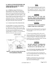
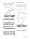
Figure 3. N30A26 Series Mounting Kit Installation Details ............................................. 9
Figure 4. Installation of N30A26 Series Mounting Kit and Beacon .............................. 10
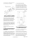
Figure 5. Mounting Hole Template for N30A21A Mounting Kit .................................... 10
Figure 6. N30A21A Mounting Kit and Beacon Overall Dimensions ............................. 11
Figure 7. Method of Installing the N30A21A Mounting Kit............................................ 11
Figure 8. Securing Beacon in N30A21A Mounting Kit .................................................. 11
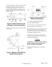
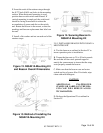
Figure 9. N30A29 Mounting Kit Installation Details....................................................... 12
Figure 10. Installation of N30A29 Series Mounting Kit and Beacon ............................ 13
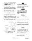
Figure 11. Mounting Hole Template for N30A21A Mounting Kit .................................. 13
Figure 12. N30A21A Mounting Kit and Beacon Overall Dimensions ........................... 14
Figure 13. Method of Installing the N30A21A Mounting Kit.......................................... 14
Figure 14. Securing Beacon In N30A21A Mounting Kit ................................................ 14
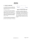
Figure 15. Nominal Pulse Train ....................................................................................... 15
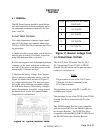
Figure 16. Typical Beacon Label..................................................................................... 16
Figure 17. Beacon Voltage Code .................................................................................... 16
Figure 18. Battery End Cover Removal With Vise Clamp and Spanner Wrench ........ 19
FIGURE 19. Battery Kit..................................................................................................... 19
Figure 20. Beacon Exploded View Showing Relative Location of Battery and Related
Parts ............................................................................................................................. 20
Figure 21. RBB Label Placement ................................................................................... 21
Figure 22. Beacon Off-Current Test Set-Up ................................................................... 21