


Copyright © 2007 Draper Inc. Form Revelation220V_Inst07 Print ed in U.S.A.
Continued on page 2
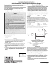
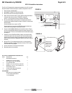
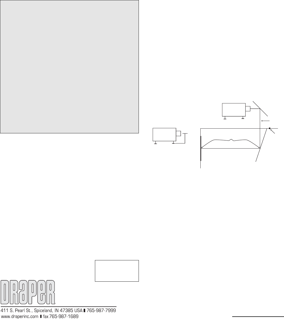
Formula to fi nd m
(mounting point is back edge of rough cut
farthest away from projection screen).
y = 15" + CL z = TD – y m = z + 8"
where: CL = centerline of lens to bottom feet
TD = throw distance
Accuracy: ± 6"
= C
L
m
y
z
Installation/Operating Instructions
220 V Revelation Video Projector Mount by Draper
These Installation/Operating Instructions are available in the offi cial language
of the country where you purchase the product. Please contact your
distributor to request a copy.
Vous pourriez demander les instructions d’installation et d’opération traduises
dans la langue offi cielle du pays ou vous achetez le produit. Veuillez
demander à votre distributeur.
Die Gebrauchsanweisung für Installation und Konstruktion sind in der
offi ziellen Sprache des Landes, indem Sie das Produkt gekauft haben,
vorhanden. Fragen Sie die jeweilige Verkaufs-Abteilung.
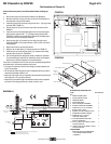
As Soon As Revelation Arrives
➀ Open carton and inspect for damage.
➁ Locate the following parts:
A. The unit itself
B. Controls
Planning
➀ Based on screen location and projector specifi cations, determine proper
position for projector installation. (First see "Choose a pro jec tor based
on its light path" on page 3. Then read "Where to install the
Revelation" below.)
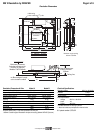
➁ Confi rm that there is at least 458mm available above the ceiling for Model
B or 347mm for Model A, if plenum housing is used. If no ple num, the
minimum clear ance is 331mm for both models.
➂ Arrange to provide service access to electrical control box and plenum
housing.
➃ If connecting duct work to the plenum housing, plan for position and length
of duct work. (See guidelines under "Installing the Plenum Kit" on
page 6.)
Caution
➀ Read instructions completely before proceeding.
➁ Follow instructions carefully. Installation contrary to instructions
invalidates warranty.
➂ Take great care when handling both fi rst surface mirrors. They will
usually come covered with a protective fi lm. Remove this fi lm after
installation and prior to projecting images. If cleaning is nec es sary, do
so very lightly with glass cleaner and a soft, lint free cloth.
➃ Do not obstruct operation of door with fi ngers or any object. Serious
injury or damage could result.
➄ The Revelation is not designed to act as a structural support of ceiling
framing. However, the trim frame is designed to support ceiling T-grid,
tiles and drywall. Equip ment should not be al lowed to rest on door
at any time.
➅ Entire bottom of unit must be unobstructed to permit proper op er a tion.
Suffi cient clearance (432mm minimum) must be allowed below door.
➆ A minimum clearance of 458mm is required above ceiling level for
model B or 347mm for Model A, if plenum housing is used. If no ple num,
the minimum clear ance is 331mm for both models.
➇ Unit must be installed level (use a carpenter’s level).
➈ Unit operates on 220 V a.c. 60 hz. current.
Note: Unit has been thoroughly inspected and tested at factory and found
to be operating properly prior to shipment.
Metric Conversion
1 inch = 25.4 mm
1 inch = 2.54 cm
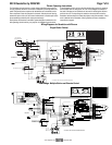
Where to install the Revelation
To determine where to mount the Revelation, you need to know the fol low ing:
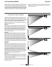
➀ The projector manufacturer’s rec om mend ed throw distance (TD). Typically,
a minimum and maximum range is provided per screen size. Select a
throw distance that is 6" greater than the minimum and 6" less than the
maximum stated. We recommend the average of the two numbers. For
example, if the range given is 228" max. and 142½" min., then use a
number between 222" and 148½". We rec om mend using the average of
185¼" as the TD.
➁ The distance from the center line of the lens to the bottom of the projector’s
feet (CL). To fi nd the mounting point (m = back edge of the rough cut) use
the fol low ing formula:
y = 15" + CL z = TD – y m = z + 8"
Remember:
CL = Distance from center line of lens to bottom of pro jec tors feet.
TD = Manufacturer’s hor i zon tal throw dis tance for the se lect ed screen size.
m = Calculated mounting point (mounting point is back edge of rough cut as
measured from screen surface.)
As an example, if you are using a pro jec tor with recommended throw distance
(TD) of 185¼" for a 100" diagonal image, and its CL di men sion is 4", calculate
the mounting point as follows:
y = 15" + CL z = TD – y m = z + 8"
y = 15" + 4" z = 185¼" – 19" m = 166¼" + 8"
y = 19" z = 166¼" m = 174¼"
In the example above, the distance from the screen to the back edge of the
rough cut would be 174¼". (Formula has a ± 6" accuracy).
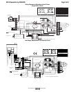
Hanging Unit
The Revelation may be installed in a variety of ways. Typically, it is re cessed
above the ceiling and supported by six (6)
3
/
8
" threaded mount ing rods. The
bottom of the main pan should be recessed ap prox i mate ly 76mm above
the fi nished ceiling. The threaded rods should pass through mount ing holes
supplied in each corner and secured by nuts above and below. The unit
should then be guy wired or blocked to prevent swing ing.
All installations should observe the following guidelines:
➀ Installer must ensure that all fasteners and supports are of ad e quate
strength to securely support Revelation and pro jec tor.
➁ Fastening methods must be suitable for mounting surface, and se cure ly
anchored so that vibration or abusive pulling on unit will not weaken
installation.
➂ Unit should be level, with weight shared more or less equally by all six
threaded mounting rods.