


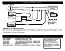
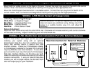

WIRING: 3-PIN Connector
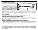
White/Red: Tachometer Input
When installing this system in TACH REFERENCE mode, this wire must be connected to a valid source of AC
voltage. This wire allows the unit to sense the engine running. See Tach Section on Page 15 for more information.
Black: Chassis Ground
Connect to body metal of the vehicle using a sheet metal screw and a star washer to ensure a good ground. Keep
the Ground wire short. Scrape away and paint or debris from ground location.
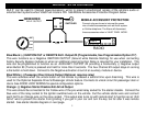
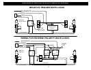
WHITE: +12V or (-) 500mA NEGATIVE PARKING LIGHT OUTPUT:
Connect to vehicle parking light circuit at the back of light switch or if this is not possible, connect directly to one of
the parking lights at the front of the vehicle. If your vehicle has a multiplex lighting system that requires a (-)
Negative parking light output, then move the jumper from (+) to (-). See Jumper Pin Diagram (Pg. 26). Some
European vehicles require separate left and right circuits. Use a dual relay or diodes to isolate the output.
NOTES: (1) Default parking light output is +12 volts. (2) Use an external relay for vehicles that draw excess
current from extra running lights, light bars, or trailers. Parking light output is limited to +10 or -.5 AMPS
only.
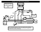
WIRING: 5-PIN Connector
Violet: (+) Door Pin Switch Input
Same as the GREEN wire below except this wire is used for vehicles that show a positive voltage (+12 volts) when
the door is open and a ground when doors are closed as in many Ford, Lincoln, and Mercury vehicles.
Green: (-) Door Pin Switch Input
Identify the wire that reads ground when any door is open and 12 volts when all doors are closed. Some vehicles
may have isolated door triggers. In this case you may need to run additional wires from other doors or go directly to
the wire that triggers the vehicle’s interior dome light. Sometimes newer vehicles contain a separate body control
module (BCM) where the door trigger circuit can be located. Most vehicles will NOT require the use of BOTH Green
and Violet door trigger wires.
Blue: (-) Hood/Trunk Pin Switch Input
Input trigger for a grounding hood or trunk pin switch. Connect to existing hood and trunk pin switches that read
ground when open. If no existing switches are available, install new pin switches if desired. Note: DO NOT mount
new pin switches in water pathways.
8