


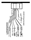
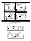

COMPONENT MOUNTING
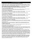
SIREN: Mount the siren under the hood to an inner fender-well, wheel-well, or other body surface with the
open end facing downward. Run the red siren wire through the firewall using a rubber grommet. Ground the
black to the body metal near the siren or you can use one of the siren’s mounting screws for a ground.
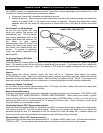
LED/VALET POD: This system includes a unique assembly that houses the LED and the
VALET/PROGRAMMING button. See page 7.
Dual-Stage Shock Sensor: Mount shock sensor with wire ties to an under dash wire harness or fasten with
screws to firewall or side paneling. Use the adjustment screw to set the sensitivity of the sensor. One screw
adjusts both levels.
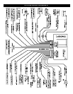
WIRING
PIN 1: BLACK WIRE: INPUT FROM VALET SWITCH
Connect to the 2-pin blue Valet Button harness to the 2-pin socket in system’s the main wire loom
PIN 2: BLUE WIRE: (-) HOOD/TRUNK TRIGGER INPUT
Input trigger for a grounding hood and/or trunk pin switches. Connect to a hood and/or trunk pin switch that
reads ground when open. If no existing switches or circuits are available, install new grounding pin switches if
desired. To avoid water leakage and failure resulting from rust, DO NOT mount switches in water pathways.
PIN 3: WHITE/RED WIRE: (-) AUX REMOTE OUTPUT #2 (Optional, Programmable)
Connect to the negative activation circuit of an auxiliary device or accessory. This output can be configured for
PULSED, TIMED, or LATCHED. See Programming Options Section for more information.
PIN 4: VIOLET WIRE: (+) DOOR TRIGGER INPUT
Connect to Positive type door switches that show +12 Volts when the door is open and Ground when the doors
are closed. Positive type door switches are found on many Ford, Lincoln and Mercury vehicles.
PIN 5: YELLOW WIRE: IGNITION SWITCHED “ON” +12 VOLTS INPUT
Connect to an Ignition Wire (or Fuse in the fuse box) that shows +12 Volts power when the key turned “On”,
when the car is “Cranking”, and when the car is running.
PIN 6: BLUE/BLACK: SENSOR #2 INPUT
Connect to the trigger wire of an optional second alarm sensor. The system main wiring loom is pre-
assembled with an extra 4-pin sensor connector for the additional sensor. (Pre-wired Sensor #2 harness
colors: Red: 12+, Black: Ground, Blue: Pre Warn, Blue/Black: Trigger input)
PIN 7: GREEN WIRE: (-) DOOR TRIGGER INPUT
Connect to Negative type door switches that read ground when a door is opened and 12 volts when all doors
are closed or connect to the circuit that triggers the vehicle’s dome light.
PIN 8: ORANGE: SHOCK SENSOR INPUT
Connects to the trigger wire of the dual-stage shock sensor sensor. The system main wiring loom is pre-
assembled with a 4-pin sensor connector for the shock sensor. Simply mount the shock sensor, plug in, and
adjust. (Pre-wired Shock sensor harness colors: Red: 12+, Black: Ground, Blue: Pre Warn, Orange Trigger
input)
PIN 9: BLUE WIRE: (-) PRE-WARN INPUT
Warn-away input for both Shock Sensor and Sensor #2. Pre-wired to 4 pin mini harnesses, no connection
required.
PIN 10: BLACK WIRE: CHASSIS GROUND
This BLACK WIRE must be connected to the CHASSIS METAL of the VEHICLE. Scrape away any paint or
debris to ensure a good connection. Use a star washer to ensure a good ground connection. Keep the
Ground wire short.
PIN 11: BROWN WIRE: (+) SIREN OUTPUT (3 Amp Max.)
Connect to the RED wire coming from the siren in the engine compartment.