


REMOVE MAIN SYSTEM FUSE(S) before jump starting the vehicle or charging the battery at high boost. DAMAGE
MAY OCCUR TO SYSTEM IF PROPER PRECAUTIONS ARE NOT OBSERVED.
DO NOT ROUTE ANY WIRING THAT MAY BECOME ENTANGLED with brake, and gas pedals, steering column,
or any other moving parts in the vehicle.
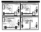
CONTROL MODULE / COMPONENT MOUNTING
DO NOT Mount the control unit or wiring harness in the engine compartment or anywhere they can become
entangled with moving parts such as brake/gas/clutch pedals, or the steering column. The alarm control module
should be mounted in a concealed location. The antenna wire should be routed away from any metal if possible.
Do not alter the length of the antenna, ground it, or route it with other wires.
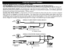
SIREN MOUNTING: Mount the siren under the hood to fender-well or other body surface with the open end facing
downward. Run the red siren wire through the firewall using a rubber grommet. Ground the black wire to the body.
LED: Mount the LED in a visible location on the dashboard or console.
Shock Sensor: Mount the included shock sensor with wire ties to an under dash wire harness or fasten with screws
to firewall or side paneling.
Override/Program Button: Mount the Override/Program push-button in a hidden but accessible location. It is used
for emergency disarm without the use of the transmitter and for programming certain features.
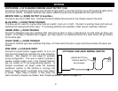
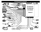
WIRING
RED WIRE: +12V POWER INPUT (15 Amp Fuse)
Connect to a +12 Volt source with the supplied fuse and fuse-holder. We recommend the connection to be at the
Vehicle’s Battery Positive Terminal.
BLACK WIRE: CHASSIS GROUND
THIS WIRE MUST BE CONNECTED TO THE CHASSIS METAL OF THE VEHICLE. Scrape away any paint or dirt
to ensure a good connection.
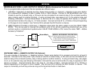
YELLOW WIRE: IGNITION SWITCHED “ON” and “START” +12 VOLTS
Connect to a (+) Ignition wire that shows +12 Volts when the key is in both the “ON” and “Cranking” positions.
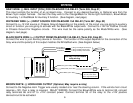
ORANGE WIRE: (-) NEGATIVE ARMED OUTPUT
This wire becomes a Negative Ground output when system is armed. This output can be used for additional starter
disable relays or to activate other devices such as scanner LED’s, window modules, voice modules etc.
3