


WIRING
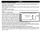
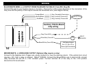
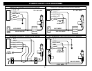
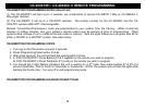
BLACK/WHITE WIRE: (+/-) OUTPUT FROM ON-BOARD 15A RELAY (Term #30, Step #3)
Connect this wire to your Auxiliary device or Function. The function of this output depends on the connection of the
Gray wire and the polarity of this output matches the White/Red wire. (See diagram below)
Orange/Black
Brown/Black
Red/Black
(-) Neg. Domelight Illumination
(-) Neg. Auxiliary Channel #1
(-) Neg. Auxiliary Channel #2
Choose One
Gray (Term #85)
White/Red (Term #87)
+12V or
Black/White (Term #30)
Dome light Illumination
Aux. #1, Aux. #2 or
15A Relay Output:
Auxiliary 15A On-Board
relay wiring
INPUT
SOURCE
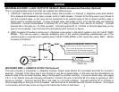
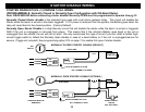
BROWN/WHITE: (-) HORN HONK OUTPUT (Optional, May require a relay)
Connect to the Negative Horn Trigger wire usually located at or near the steering column. If the vehicle horn circuit
requires +12V, then a relay is required. RELAY WIRING: Connect the Brown/White wire to terminal 85, connect
relay terminals 86 and 87 to +12V constant power. Connect terminal 30 of the relay to the +12V positive
device/circuit to be activated.
5