


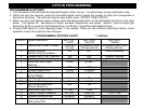

WIRING
PIN 11: YELLOW WIRE: IGNITION SWITCHED “ON” +12 VOLTS INPUT
Connect to an Ignition Wire (or Fuse in the fuse box) that shows +12 Volts power when the key turned “On”, when the
car is “Cranking”, and when the car is running.
PIN 12: ORANGE WIRE: NEGATIVE ARMED OUTPUT (500mA Ground, Optional)
This wire becomes a (-) Ground output when system is armed. This output can be used for optional accessories such
as extra sensors, window roll up modules, voice modules, etc.
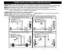
PIN 13: WHITE/RED WIRE: (-) AUX REMOTE OUTPUT 2 (Optional, may require a relay)
Connect to the activation circuit of a 2nd auxiliary device or accessory. If the circuit requires +12Volts, then a relay is
required. RELAY WIRING: Connect the White/Red wire to terminal 85 of a relay. Connect terminals 86 and 87 to +12
Volts constant power. Connect terminal 30 to the Positive activation circuit of the device or accessory.
PIN 14: BLUE WIRE: (-) HOOD/TRUNK TRIGGER INPUT
Input trigger for a grounding hood and/or trunk pin switches. Connect to a hood and/or trunk pin switch that reads
ground when open. If no existing switches or circuits are available, install new grounding pin switches if desired. To
avoid water leakage and failure resulting from rust, DO NOT mount pin switches in water pathways.
PIN 15: BROWN/WHITE WIRE: (-) HORN HONK / CHIRP OUTPUT (Optional, may require a relay)
Connect to the Negative Horn Trigger wire usually located near the steering column. If the Horn circuit requires
+12Volts, then a relay is required. RELAY WIRING: Connect the Brown/White wire to terminal 85 of a relay. Connect
terminals 86 and 87 to +12 Volts constant power. Connect terminal 30 to the Positive horn activation circuit.
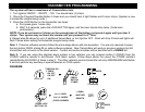
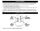
2-PIN PLUG (BLUE): PROGRAM/OVERRIDE PUSH BUTTON
2-PIN PLUG (RED): LED INDICATOR (RED FLASHING LIGHT)
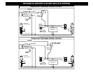
3-PIN PASSENGER DOOR UNLOCK PLUG:
GREEN WIRE: (-) PASSENGER DOOR UNLOCK OUTPUT (Optional, requires relay)
Connects to unlock circuit for passenger door(s) when using separate driver’s door unlock option. See
SEPARATE DRIVER’S DOOR UNLOCK WIRING for configuration options.
RED WIRE: NOT USED / NO CONNECTION
BLUE WIRE: NOT USED / NO CONNECTION
4 PIN SENSOR PLUG:,
SHOCK SENSOR: The sensor supplied with
this system does not require any additional
wiring. Simply mount the sensor in a suitable
location, plug it in, and adjust the sensitivity.
WHITE Wire: Negative Pre-Warning
BLUE Wire: Negative Trigger,
BLACK Wire: Sensor Ground
RED Wire Sensor +12V Power