


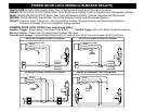
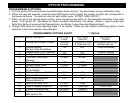

WIRING
PIN 1: GRAY WIRE: INPUT SOURCE FOR REMOTE OUTPUT 1 RELAY
Connect to a +12 Volt or Chassis Ground source depending on the output required for PIN 2 Gray wire See Below.
PIN 2: GRAY WIRE: REMOTE OUTPUT 1 On-Board Relay (Optional)
Connect this wire to an AUX device or Function. This output will provide a momentary signal when button #3 is
pressed and held for more than one second. The (+/-) polarity of this output depends on the connection of PIN 1 Gray
wire above. This wire can be used to activate a Factory power trunk release or an optional accessory not included with
this system e.g. window roll up/down modules, remote start, scanner LED’s etc.
PIN 3: BLACK WIRE: INPUT SOURCE FOR DOME LIGHT ILLUMINATION RELAY
Connect to a +12 Volt source or Chassis Ground depending on the vehicles dome light circuit. (Required for PIN 4
Black/White wire. See Below.) The connection of this wire [+12V or Ground] must be the same as dome light circuit!
PIN 4: BLACK/WHITE WIRE: DOME LIGHT ILLUMINATION OUTPUT On-Board Relay (Optional)
Connect this wire to the vehicle’s dome light circuit (May also be connected at the same point as the Door Pin Switch
input). This output will turn on the vehicle’s dome light when the system is disarmed using the remote control. The +/-
polarity of this output depends on the connection of the PIN 3 Black wire.
PIN 5: RED WIRE: +12V POWER INPUT (15 Amp Fuse)
Connect to a +12 Volt source with the supplied fuse and fuse-holder. We recommend the Battery positive terminal.
PIN 6: BROWN WIRE: (+) SIREN OUTPUT (3 Amp Max.)
Connect to the RED wire coming from the siren in the engine compartment.
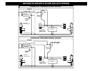
PIN 7: VIOLET WIRE: (+) DOOR TRIGGER INPUT
Connect to Positive type door switches that show +12 Volts when the door is open and Ground when the doors are
closed. Positive type door switches are found on many Ford, Lincoln and Mercury vehicles.
PIN 8: BLACK WIRE: CHASSIS GROUND INPUT
This BLACK WIRE must be connected to the CHASSIS METAL of the VEHICLE. Scrape away any paint or debris to
ensure a good connection. Use a star washer to ensure a good ground connection. Keep the Ground wire short.
PIN 9: WHITE WIRE: +12V FLASHING PARKING LIGHT OUTPUT
Connect to switched parking light wire at back of light switch. If this is not possible, connect directly to one of the
parking lights at the front of the vehicle. European vehicles require separate right and left circuits. Use a dual relay or
2 diodes to separate the output signal.
PIN 10: GREEN WIRE: (-) DOOR TRIGGER INPUT
Connect to Negative type door switches that read ground when a door is opened and 12 volts when all doors are
closed or connect to the circuit that triggers the vehicle’s dome light.