


WIRING
RED WIRE: +12V POWER INPUT (15 amp fuse)
Connect to +12 Volt source with supplied fuse & holder. Recommended location for this connection is at the
vehicle battery positive terminal.
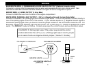
14 GA. BROWN WIRE: (On-board Starter Disable Relay)
Cut the 14GA. Brown wire in half. Connect the 2 female terminals to the Male terminals on the control
module. Cut the starter (Cranking only) wire on the vehicle. Connect the two brown wires to the 2 ends of the
Starter wires. See SYSTEM WIRING DIAGRAM on PAGE 19
2 PIN PLUG (BLUE): PROGRAM/OVERRIDE PUSH BUTTON
Mount the Valet/Programming switch in a concealed but accessible location. This button is required when
programming options and when an emergency override is required.
2 PIN PLUG (RED): LED INDICATOR (RED FLASHING LIGHT)
Mount the LED in a visible location of the dash or console.
4 PIN SENSOR PLUG/HARNESS (BLUE):
White Wire: Negative Trigger
Blue Wire: Negative Warn-away
Black Wire: Sensor Ground
Red Wire Sensor Power
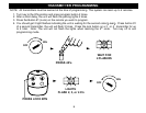
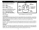
SHOCK SENSOR: The sensor supplied with this system does not require any additional wiring. Simply
mount the sensor in a suitable location, plug it in, and adjust the sensitivity. There are 2 LED’s on the shock
sensor to assist you in adjusting sensitivity. The Green LED indicates the “Warn Away” level and the Red LED
indicates a full alarm shock sensor violation.
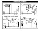
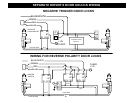
POWER DOOR LOCK WIRING
3 PIN DOOR LOCK PLUG (Optional):
GREEN: (-) Negative pulse for LOCK
RED: +12V Coil Power for using relays.
BLUE: (-) Negative pulse for UNLOCK
Hint: Determine the type of locking system the vehicle has before connecting any wires. Incorrect connection
could result in damage to the alarm and/or the vehicle’s locking system.
6