


The ML-Series Remote Battery Switch provides high-current carrying and switching under load.
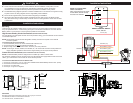
The Remote Battery Switch should be installed close to the battery banks to avoid voltage drop.
Install a single pole double throw (SPDT) or single pole single throw (SPST) control switch in a convenient
location near other electrical controls or companionway to allow quick access in the event of an emergency
(see Illustration on reverse).*
The Manual Control Override Knob provides:
• an added level of safety that allows manual ON-OFF control with or without power
• LOCK OFF for servicing the electrical system
ML– Series
Remote Battery Switch (RBS)
PN 7712 / PN 7712B / PN 7714 / PN 7714B
980010060 Rev.002
• Magnetic Latch (ML)—draws very low current (<13 mA in the ON state and <8 mA in the OFF state) and draws
moderate current for very short time when changing state
• Silver alloy contacts provide high reliability for switching live loads
• Manual control override knob provides an added level of safety allowing control with or without power,
and offering LOCKED OFF capability for servicing
• LED output to remotely indicate switch state
• Tin-plated copper studs for maximum conductivity and corrosion resistance
• Label recesses for circuit identication
• PNs 7712 and 7714 include a Remote Control Switch PN 2155
RBS Specications 7712, 7712B 7714, 7714B
Cranking Rating See Table Below See Table Below
Intermittent Rating See Table Below See Table Below
Continuous Rating See Table Below See Table Below
Amperage Operating Current When changing state <7A from Main When changing state <4A from Main
contacts returns to negative (blk) wire contacts returns to negative (blk) wire
In “ON” state 13mA, In “OFF” state 8mA When “ON” 13mA, When “OFF” 8mA
Voltage Maximum Operating 16.5V DC Max. 32V DC Max.
Live Current Switching 300A @ 12V DC—10,000 Cycles 150A @ 24V DC—10,000 Cycles
‡
Mechanical Endurance 100,000 Cycles 100,000 Cycles
Control Circuit Voltage 9–16.5V DC 8–32V DC
Terminal Stud Size 3/8"-16 (M10) 3/8"-16 (M10)
Maximum Terminal Stud Torque 140 in-lb (15.5 N•m) 140 in-lb (15.5 N•m)
Ring Terminal Size 3/8", M10 3/8", M10
Terminal Ring Diameter Clearance 1.18" (30.0mm) 1.18" (30.0mm)
Regulatory Meets ISO 8846 and SAE J1171 external ignition protection requirements, Rated IP66
Remote Control Switch 2155 Specications
Action SPDT, ON-ON
Maximum Operating Amperage 20A @ 12V DC | 15A @ 24V DC
Seals Internal & External Gasket Panel Seal
Operating Temperature Range
-
40°C to 85°C
Mounting Hole 1.450"x 0.830" (36.00mm x 21.08mm)
LED Rating 100,000 hours 1/2 life, 20 mA @ 14V
Regulatory Meets ISO 8846 and SAE J1171 external ignition protection requirements, Rated IP67
Marine Electrical Prod
ucts
PN Termination
Manual
Control
Control
Circuit
Remote Control
Switch Included
7712 Tinned Wires Yes 12V DC SPDT, ON-ON
7712B Tinned Wires Yes 12V DC -
7714 Tinned Wires Yes 24V DC SPDT, ON-ON
7714B Tinned Wires Yes 24V DC -
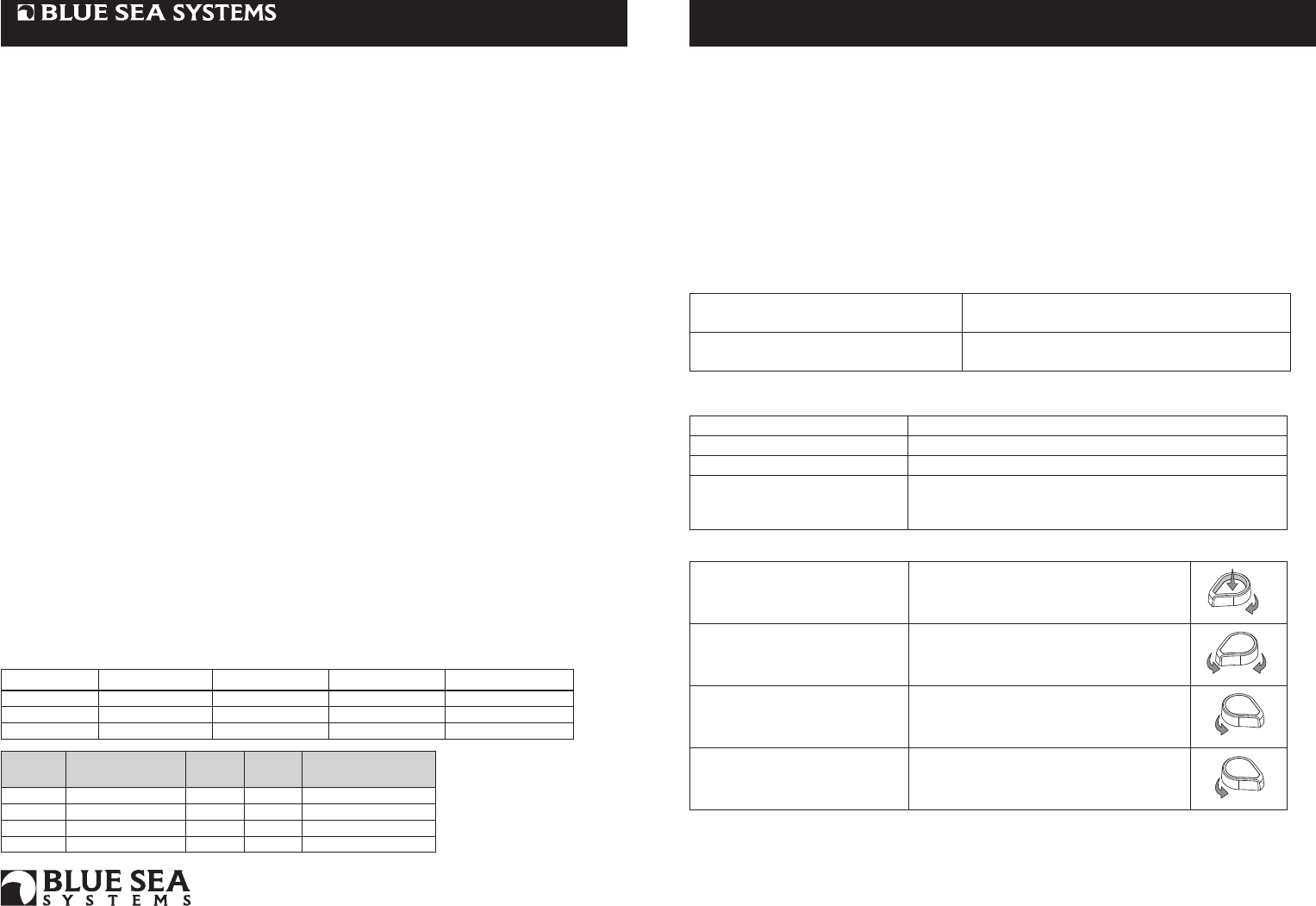
Overview of Application
To connect battery bank to load,
or combine battery banks
With Override Knob in (REMOTE position),
push button until latched (Push to Latch On).
To disconnect battery bank from
load, or isolate battery banks that
are connected
Rotate Override Knob to right to release button
from Latch On mode (button pops up). Rotate
Override Knob to left (REMOTE position).
To prevent remote operation
Rotate Override Knob to right
(LOCK OFF position).
To secure for servicing
With Override Knob in (LOCK OFF position),
pass cable tie through hole.
1
2
Wire Size (AWG) Cranking 10 sec. Cranking 1 min. Intermittent 5 min. Continuous (UL 1107)
2/0 2,000A 750A 400A 225A
4/0 2,000A 750A 400A 300A
2x (4/0) 2,500A 1,100A 700A 500A
To connect battery bank to load, or combine
battery banks
Set remote switch 2155 to position marked “ON”.
Remote LED indicates closed connection.
To disconnect battery bank from load, or
isolate battery banks that are connected
Set remote switch 2155 to position marked “OFF”.
425 Sequoia Drive
Bellingham, WA 98226 USA
p 360.738.8230
p 800.222.7617 USA and Canada
f 360.734.4195
www.bluesea.com
Remote LED Indicator embedded in PN 2155 SPDT ON-ON Contura Switch
indicates Remote Battery Switch state or condition as follows:
LED INDICATION REMOTE BATTERY SWITCH STATE OR CONDITION
LED is OFF Remote Battery Switch is OFF
LED is ON Remote Battery Switch is ON
LED double blinking ON-OFF
Manual override--check Remote Battery Switch for switch states.
OR Remote Battery Switch mechanical failure
‡
Predicted performance
* Although a SPST switch may be used if desired, use of a SPDT switch improves immunity to inadvertent
switching if the controls become damp.
Emergency Manual Control Override Operations
The remote LED embedded in PN 2155 indicates a closed connection between battery bank and load, or
between two battery banks when used as an emergency cross-connect.
Remote Operation. PN 2155 (SPDT, ON-ON) Remote Control Contura Switch in the ON position can either
connect the battery bank to the load or combine two battery banks. In the OFF position it can either
disconnect a battery bank from a load or isolate two batteries from each other.