


1
Before you begin installation
• Read the INSTRUCTIONS!
• Always use a multi-meter when verifying vehicle
wiring.
• Before mounting, verify the customer’s desired
location for the valet switch and LED.
• Always look before drilling. Make sure you will
not damage vehicle hoses, electrical looms or
exterior body panels.
Installation Notes
• Make all wiring connections to the vehicle
before connecting the harness to the main unit.
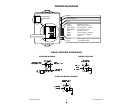
• Mount the main unit in a secure area, away from
vehicle computers and heating/air conditioning
ducts.The location should be convenient for your
installation, but hidden from thieves. Mount the
unit as far away from metal objects as possible to
increase the range of the remote transmitters. Do
not
install the main unit in the engine
compartment.
• When running the harness wires through the
vehicle, be careful to run them where they cannot
be damaged or shorted. Keep them away from any
moving parts or areas of high heat. Use rubber or
plastic grommets to protect the harness wires
where they pass through holes in metal panels.
• Secure the shock sensor to the steering
column, thick wire harness or a dash brace, using
a wire tie. Make sure that the adjustment screw is
accessible for later testing and adjustment.
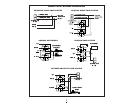
8-Pin Harness:
• VIOLET WIRE - Auxiliary output (-) 300mA.
Connect to an optional relay for trunk release,etc.
• ORANGE WIRE - Siren output (+) 1A.
Connect to the siren’s red wire. Connect the
siren’s black wire to ground.
• BLACK/YELLOW WIRE - Armed Output (-)
300mA. Connect to a relay for optional starter
defeat (See installation diagrams).
• BLACK/WHITE WIRE - Negative door trigger
(-). Connect to the door switch circuit wire that
shows ground when the door is open.
• PINK WIRE - +12V Ignition input. Connect to
the main ignition wire at the ignition switch
harness that shows +12V when the ignition is on
and while cranking.
• WHITE WIRE - Unlock output (-) 300mA.
• BROWN WIRE - Lock output (-) 300mA.
• BLACK WIRE - Ground input (-). Connect to a
solid chassis ground that is clean and free of paint.
2-Pin Harness:
• YELLOW WIRES - Parking Light output (+) 7A
relay. For vehicle’s with a single parking light
circuit,connect one YELLOW wire to the vehicle’s
parking light wire and insulate the other YELLOW
wire. For vehicle’s with independent left and right
parking light circuits, connect one YELLOW wire
to each side circuit.NOTE: Do not connect to the
vehicle’s headlight circuit.
• RED WIRE - +12V Battery input. Connect the
red wire to a constant +12V source.
INSTALLATION MANUAL
BW1700
VEHICLE SECURITY SYSTEM
VEHICLE SECURITY SYSTEMS