


© 2005 Directed Electronics, Inc. Vista, CA
1111
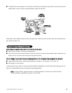
An accessory wire will show +12V when the key is in the accessory and run positions. It will not show +12V during
the cranking cycle. There will often be more than one accessory wire in the ignition harness. The correct accessory
wire will power the vehicle's climate control system. Some vehicles may have separate wires for the blower motor and
the air conditioning compressor. In such cases, it will be necessary to add a relay to power the second accessory wire.
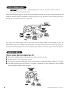
To test for a tachometer wire, a multimeter capable of testing AC voltage must be used. The tachometer wire will
show between 1V and 6V AC. In multi-coil ignition systems, the system can learn individual coil wires. Individual
coil wires in a multi-coil ignition system will register lower amounts of AC voltage. Also, if necessary, the system
can use a fuel injector control wire for engine speed sensing. Common locations for a tachometer wire are the
ignition coil itself, the back of the gauges, engine computers, and automatic transmission computers.
IIMMPPOORRTTAANNTT!!
Do not test tachometer wires using a test light or logic probe (computer safe test light)!
This will damage the vehicle.
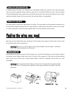
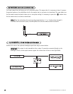
HHooww ttoo ffiinndd aa ttaacchhoommeetteerr wwiirree wwiitthh yyoouurr mmuullttiimmeetteerr::
1. Set to ACV or AC voltage (12V or 20V is fine).
2. Attach the (-) probe of the meter to chassis ground.
3. Start and run the vehicle.
4. Probe the wire you suspect of being the tachometer wire with the red probe of the meter.
5. If this is the correct wire the meter will read between 1V and 6V.
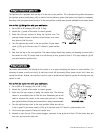
In diesel vehicles it is necessary to interface with the wire that turns on the WAIT TO START light in the dash-
board. This wire illuminates the bulb until the vehicle’s glow plugs are properly heated. When the light goes out
the vehicle can be started. This wire is always available at the connector leading to the bulb in the dashboard.
It can also be found at the Engine Control Module (ECM) in many vehicles.
TToo tteesstt aanndd ddeetteerrmmiinnee tthhee ppoollaarriittyy ooff tthhiiss w
wiirree::
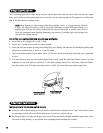
1. Set your multimeter to DCV or DC voltage (12 or 20V is fine).
2. Attach the (+) probe of the meter to (+)12V.
3. Probe the wire that you suspect leads to the bulb with the (-) probe of the meter.
4. Turn the ignition switch to the ON position.
5. If the meter indicates 12 volts until the light goes out you have isolated the correct wire and the wire's polar-
ity is negative (ground while the bulb is on).
6. If the meter reads zero volts until the light goes out and then reads 12 volts, you have isolated the correct
wire and the wire's polarity is positive.
ffiinnddiinngg tthhee wwaaiitt--ttoo--ssttaarrtt bbuullbb wwiirree ffoorr ddiieesseellss
ffiinnddiinngg tthhee ttaacchhoommeetteerr wwiirree
ffiinnddiinngg tthhee aacccceessssoorryy wwiirree