


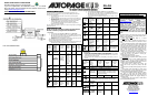
7-PIN MAIN WIRE HARNESS
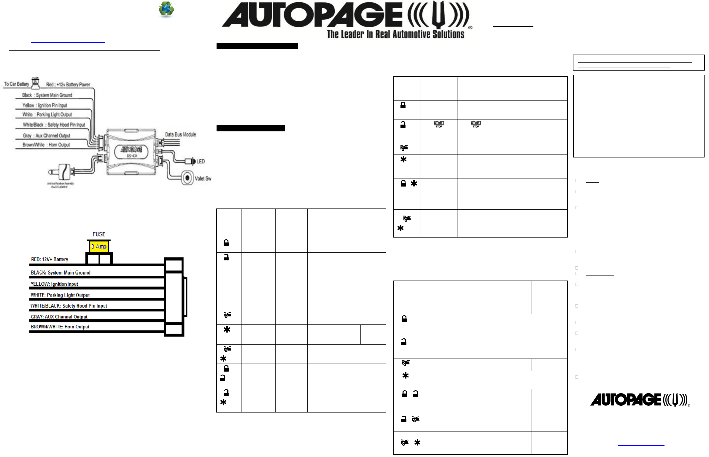
B programming
1. Turn the Ignition switch „ON/OFF‟ 3 TIMES and stay in OFF position.
2. Push the Valet switch 5 times (holding in on the 5
th
push) until LED flashes &
two chirps with one long chirp is heard then release the valet switch. You are
now in the Alarm feature “B” programming mode.
3. Press and release the transmitter button corresponding to the feature you want
to program.
Press
Transmitter
Button
One Chirp /
LED one pulse
Factory Default
Setting
Two Chirps /
LED two
pulses
Three Chirps /
LED three
pulses
Four Chirps /
LED four pulses
1
Constant
parking light
output upon
Remote Start
Flashing
parking light
output upon
Remote Start
2
Press
button twice =
Activate Remote
Start.
Press
button once =
Activate
Remote Start.
3
20 minutes run
time
30 minutes
run time
10 minutes run
time
5 minutes run time
4
Door lock before
start
Door lock
after shut-
down
Door lock
before start
and Door lock
after shut-
down
Without this feature
5 +
Channel 3
Output =
Pulsed output
(XT74 Upgrade Kit
must be used to
access this
feature)
Channel 3
Output =
Latched
output
Channel 3
Output =
Latched output
and reset with
ignition “on”
Channel 3 Output =
Timer programming (set
to any interval between
1 second and 2
minutes.)
6 +
CH 4 output =
Momentary
output
(XT74
Upgrade Kit must
be used to access
this feature)
CH 4 output
= Latched
output
CH 4 output
= Latched
output and
reset with
ignition ON
CH 4 output = Timer
programming (set to
any interval between
1 sec. to 120 sec.)
Exit: Turn Ignition to 'ON' position, or leave it for 15 seconds. 3 long chirps & 3 parking
light flashes will confirm exit.
C Programming
1 Turn the Ignition 'switch „ON/OFF‟ 3 TIMES and stay in OFF position.
2 Push the Valet switch 7 times (holding in on the 7th push) until LED flashes & three
chirps with one long chirp is heard then release the valet switch. You are now in the
Alarm feature “C” programming mode.
3 Press and release the transmitter button corresponding to the feature you want to
program.
Press
Transmitter
Button
One Chirp /
LED one
pulse
Factory
Default
Setting
Two Chirps /
LED two
pulse
Three Chirps
/
LED three
pulse
Four Chirps /
LED four
pulse
1
Exit the programming mode. (3 long chirp & 3 parking light
flashes to confirm this exit.)
2
A> RPM learning – see RPM Learning page 26.
B>
Start
Crank Time:
0.6-second
0.8-second (2 chirps), 1.0-second (3 chirps),
1.2-second (4 chirps), 1.4-second (5 chirps),
1.6-second (6 chirps), 1.8-second (7 chirps),
2.0-second (8 chirps), 3.0-second (9 chirps),
4.0-second (10 chirps),
3
Low check
level
Hi check level
4
Start or Stop the system for TESTING & ADJUSTMENT
5
+
Data Bus
Interface
Mode**
Timer
checking
6 +
+ 50 RPM
DBI ONLY
No RPM
learning
7 +
- 50 RPM
DBI ONLY
No RPM
Learning or <
50RPM
DS-434
QUICK START INSTALLATION GUIDE
Help Auto Page protect our environment !
If you are not proficient in the installation of this product or would
like a full version of the installation manual, Please visit our web
site @ www.autopageusa.com
FOR PROFESSIONAL INSTALLATION ONLY!
PROGRAMMING TRANSMITTER
Note: This model will only retain the last 4 remote transmitters programmed. If the
transmitter memory is exceeded, the security system will start deleting transmitters from
memory in chronological order.
1. Turn the Ignition 'switch „OFF/ON‟ 3 TIMES and stay in the ON position.
“Within 15 seconds”.
2. Push the Valet switch 2 times and hold it on the 2nd push until LED flashes and
long chirp is heard then release the valet switch. You are now in the Transmitter
programming mode.
3. Press and hold any button of the transmitter until the siren responds with a
confirming chirp indicating the signal has been stored into memory.
If you have additional transmitters (up to 4) that need to be programmed,
repeat step 3 for each transmitter.
Exit: Turn Ignition to 'OFF' position, or leave it for 15 seconds. 3 long chirps & 3 parking light
flashes will confirm exit.
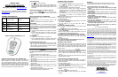
FEATURE PROGRAMMING
NOTE: An XT-33 transmitter must be programmed to
the unit in order to program the unit features!
A Programming
1. Turn the Ignition 'switch „ON/OFF‟ 3 TIMES and stay in OFF position.
2. Push the Valet switch 3 times (holding in on the 3
rd
push) until LED Flashes &
one chirp with one long chirp is heard, then release the valet switch. You are
now in the Alarm feature “A” programming mode.
3. Press and release the transmitter button corresponding to the feature you want
to program.
a. The siren chirps and LED pause will indicate previously setting.
b. The factory default settings is always [1] LED flash, [1] chirp.
4. Depress the transmitter button to change the feature. Simply keep re-depressing the
transmitter button until the system advances to your desired setting.
Press
Transmitt
er
Button
One Chirp /
LED one
pulse
Factory
Default
Setting
Two Chirps /
LED two
pulses
Three
Chirps /
LED three
pulses
Four
Chirps /
LED four
pulses
Five
Chirps
and five
LED
blinks
1
Factory
alarm disarm
with CH 3 ON
Without this
feature
2
Pathway
Illumination
Feature “off”
Parking light
turns “on” for
30- second
upon an
unlock signal
Parking
light turns
“on” for
30-
second
upon an
unlock
signal &
10-second
upon a
lock
signal.
3
DBI Unlock
ALL doors
DBI Two step
unlock
4
AUX 2 =
Trunk
Aux 2 = CH4
Ground
out when
running
Ground
out when
running
Ground
out when
start
5 +
Horn output
Aux 1 = CH4
Ground
out when
running
Ground
out when
running
Ground
out when
start
6 +
Lock/Arm &
Unlock/Disar
m
Confirmation
Chirp
Lock/Arm
Confirmation
Only
All chirps
OFF
7 +
Without
ignition
controlled
door locks &
unlocks
Ignition
controlled
door locks &
unlocks
Ignition
controlled
door
locks
only
Ignition
controlled
door
unlocks
only
Exit: Turn Ignition to 'ON' position, or leave it for 15 seconds. 3 long chirps & 3 parking light
flashes will confirm exit.
960 Knox Street Unit B
Torrance, California 90502
Main Office: 310-323-1800
Technical Support: 800-945-2527
(For Authorized Dealers Only)
www.autopageusa.com
FEATURE “C” MUST BE PROGRAMMED FOR THE
UNIT TO RESPOND TO REMOTE START!
If you are not sure or do not understand any part of
the quick start guide, please download the complete
installation manual available at
www.autopageusa.com . This quick start guide is a
brief outline for professional installers that are
familiar with the installation and operation of this
remote start system. Please test all of your
installation to insure proper operation of the vehicle
before returning it to the customer.
For authorized dealer technical support, please call
800-945-2527 and wait for the first available
technician. Technical support hours are Monday
through Saturday from 8:00 to 5:00 Pacific standard
time.
This Remote Starter with Keyless Entry System has been
designed to be installed on fuel-injected vehicles with an
automatic transmission ONLY.
Never install this remote starter on a manual
transmission vehicle.
This system must be installed and wired through a
safety switch so it will not start in any forward or reverse
gear.
Some automatic transmission vehicles mainly older GM
vehicles with a purple starter wire have a mechanical-type
park safety switch instead of electrical safety switch. The
mechanical type does not interrupt the starter circuit when
the transmission is in any gear and does not offer the 100%
level of safety required for remote starting purposes.
Therefore, our system should never be installed on any
vehicle that uses a mechanical type park safety switch.
Once you install this system, you must verify that the
vehicle will not start in any forward or reverse gear,
regardless of the type of vehicle.
Read the operation manual for operating.
Do not install any component near the brake, gas pedal
or steering linkage.
Some vehicles have a factory installed transponder
immobilizer system that can severely complicate the
installation. There is a possibility that this system cannot be
installed on some immobilizer-equipped vehicles.
Most vehicles have an SRS air bag system. Use
extreme care and do not probe any wires of the SRS
system.
Disconnect the car battery before beginning work on the
vehicle.
Check behind panels before drilling any holes. Ensure
that no wiring harness or other components are located
behind the panels that would otherwise be damaged.
Do not use conventional crimp lock, bullet on any wiring.
Poor wiring, i.e. taped joints will possibly introduce
unreliability into the alarm system and may result in false
alarms or incorrect operation. We suggest soldering all
connection points.
Install the wiring neatly under carpets or behind trim to
prevent possible damage to wires.