


TH140-28 400-140-000-C 2008-01-15 1/4
1.1 Guidelines
TURN OFF POWER TO THE HEATING SYSTEM AT THE MAIN
POWER PANEL TO AVOID ELECTRICAL SHOCK.
Installation should be carried out by an electrician.
• For a new installation, choose a location about 5 ft. (1.5 m) above
the floor.
• The thermostat must be installed facing the heating system and on
an inside wall.
• Avoid locations where there are air drafts (top of staircase, air out-
let), dead air spots (behind a door), direct sunlight or concealed
chimneys or stove pipes.
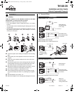
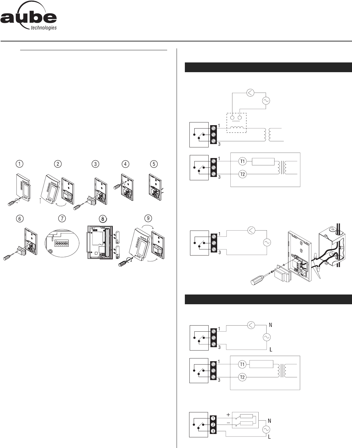
n Loosen the captive screw holding the faceplate to the mounting
plate.
o Pull the lower part of the faceplate to remove it from the mount-
ing plate.
p Loosen the screw (captive) holding the wire cover and remove
the wire cover.
q Pull wires through the hole in the mounting plate and secure the
mounting plate to the wall (or onto an electrical box for line volt-
age wiring) using the enclosed wall anchors and screws.
r Wire the thermostat to the heating system (see section 1.2) and,
if necessary, connect the remote input (see section 1.3).
s Once wiring is complete, re-install the wire cover.
t Use the switches located at the back of the faceplate to config-
ure your thermostat (see section 1.4) according to your applica-
tion.
u Install the batteries (see section 1.5).
v Mount the faceplate on the mounting plate and tighten the screw.
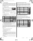
1.2 Thermostat Wiring
LOW VOLTAGE < 30 V: no polarity
LINE VOLTAGE 120 to 240 VAC
Must be installed onto a certified electrical box.
For a 2-wire connection: no polarity
For a 3-wire connection: observe the polarity
n
Installation
1.
NORTH AMERICA
EUROPE
Connection to a
circulator through
a 24 V relay
Connection to the
thermostat terminals
of a furnace
120/240 V
Relay
24 V transformer
Relay
Furnace
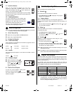
Connection to a
circulator (pump)
of a water heating
system
2 A maximum load
120/240 V
Power supply
Load
Provided wires
Direct wiring to
the circulator
Connection to the
thermostat terminals
of a furnace
240 V
Furnace
Relay
Wiring to a
power-operated
mixing control valve
240 V
TH140-28
Installation and User Guide
Electronic Programmable Thermostat
400-140-000-C (TH140-28) ENG.fm Page 1 Tuesday, January 15, 2008 1:46 PM