


1
SAFETY ALERT SYMBOLS
Safety Symbols alerting you to potential personal safety hazards. Obey all safety
messages following these symbols.
ƽ WARNING ƽ CAUTION
avoid possible avoid possible
injury or death injury and/or property damage
FOR YOUR SAFETY READ ALL INSTRUCTIONS
BEFORE INSTALLATION AND OPERATION
Installer: Provide these instructions to the consumer.
Consumer: Keep documents for future reference.
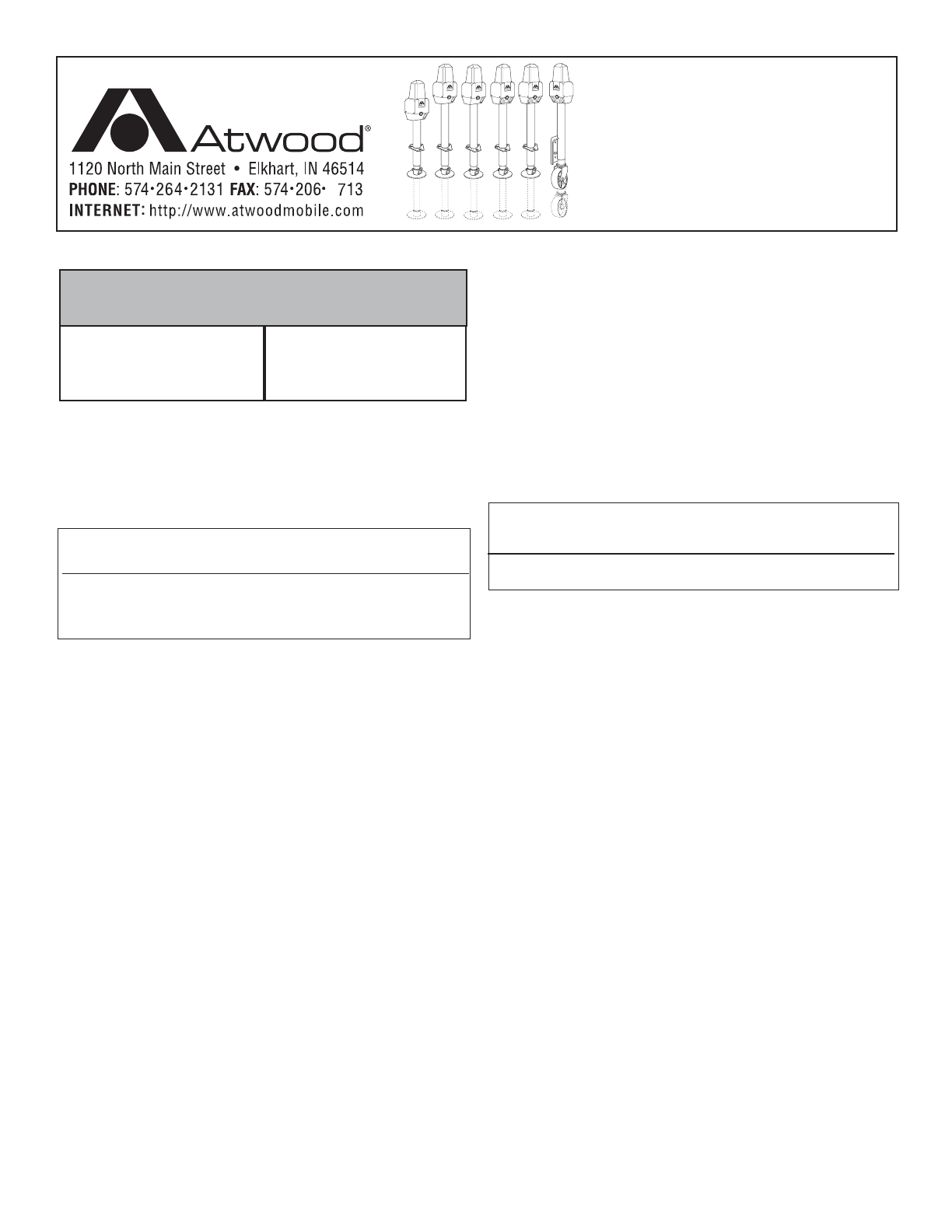
The Atwood Power Jack is a 12-volt DC motor driven screw jack
intended for use on recreational type and marine trailers. Patent #
D349800. Jack is used to level trailer or raise and lower coupler for
hookup to tow vehicle.
ƽ CAUTION
PERSONAL INJURY/PROPERTY DAMAGE
• Retract jack fully before towing.
• Do not use blocks to increase height of jack.
• Use 3500 lb. Heavy Duty Power Jack if you use equalizer bars
between the trailer and the tow vehicle.
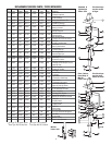
LIGHT WT STANDARD DELUXE HEAVY DUTY MARINE
SHORT
Max. Lifting Cap. LBS 1500 2500 2500 3500 1000
INSTALLATION
1. Block tires of trailer and securely support trailer tongue.
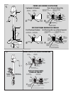
2. The Atwood RV Power Jack is designed to attach to the top
surface of an A-frame type tongue having mounting holes typical
of the Atwood A-frame couplers FIG 1. Use coupler installation
instructions (MPD 87984) if installing coupler. The Marine Power
Jack attaches to the side of a straight tongue trailer.
3. A lower support plate must be used for side support of the RV
jack on the lower surface of the A-frame
FIG 1.
HOLE DIAMETERS: Light Weight 2.02˝ (MIN) 2.09˝ (MAX)
Standard / Short / Deluxe / Heavy Duty 2.20˝ 2.28˝
Hole in lower support plate must align with hole in coupler.
TO ORDER LOWER SUPPORT PLATE: Light Weight - Atwood MPD 80263
Standard / Short / Deluxe / Heavy Duty - Atwood MPD 80570
Using 1/8˝ fillet weld, No. E6011 AWS welding rod 1/8˝ diameter,
machine amps (AC or DCRP) at 160-180 with 50 volts, weld
plate full length on each side to underside of A-frame. The
maximum frame height is 6 inches.
4. Place RV jack through holes in coupler and lower support plate,
FIG 1-A. Attach with three (3) bolts (3/8˝ dia. x 5/8˝ long, grade 5,
(provided) FIG 1-B. NOTE: Torque bolts to 15 foot lbs. minimum
/20 foot lbs. max.
Note: There must be metal to metal contact between jack and coupler.
The three mounting bolts with attached star washers must be used.
The star washers are designed to remove paint on the surface of
jack flange. The bolts also should remove paint from the mounting
holes in coupler. If there is a grounding problem (i.e. no power) check
these two surfaces to be sure there is metal to metal contact between
jack and coupler. For wiring, see WIRING ILLUSTRATIONS
FIG 2 & 3.
5. Attach Marine Jack as shown.
6. Route wire lead from motor along trailer tongue to battery.
Secure lead to jack housing and trailer frame using cable ties or
equivalent.
7. Remove fuse from fuse holder. Connect the wire lead from the
jack directly to the positive (+) terminal of the battery. Replace
the fuse into the fuse holder.
For auxiliary battery, connect lead to auxiliary battery positive (+)
terminal so that jack may be used when connected to 115v. For
additional wire, use #10 stranded copper wire or larger.
8. After reinstalling fuse, check installation by pressing switch marked
“EXT” for jack extension or “RET” to retract the jack.
9. On the Short, Deluxe, Heavy Duty or Marine power jacks, check
utility light by moving switch to “ON” or “OFF”.
ƽ CAUTION
HAND OR FINGER INJURY
• Hold foot pad near the bottom of the tube, when installing foot
pad or caster.
10. Place foot pad, or caster for Marine power jack, over the end of
jack, align holes, and place pin through holes. A cotter pin clip
goes through the hole in the pin, preventing pin from coming out.
OPERATION
1. To raise or lower jack, press switch marked “EXT” or “RET”.
“Extend” and “Retract” refer to the jack, not the trailer.
2. Release switch when jack nears full retraction or full extension to
prevent unnecessary wear on motor clutch.
a. When jack reaches its maximum extended or retracted length
or maximum load, a clicking noise will be heard. This is the
overriding clutch built into the motor to prevent overload.
Release switch immediately when clicking is heard. If the jack
has been over extended or retracted, it may bind. If so,
operate with the manual override handle, per
STEP 3 below, to
break it free.
b. When the heavy duty power jack is being retracted, there may
be some audible noise, coming from the brake area. This is
normal and is due to the high load for which this jack is rated.
3. In case of electrical failure- raise or lower jack as follows:
STANDARD & LIGHTWEIGHT POWER JACKS
a. Remove top cover by loosening the four screws.
b. Remove screws holding motor to mounting plate.
c. Lift motor off jack.
d. Turn hex drive nut with wrench or optional manual drive
handle, part # 87891 (
FIG 1-C).
e. To reinstall electric motor on jack, rotate hex drive nut so the
pin in the hex drive nut aligns with slot in motor drive shaft.
f. Tighten hex nut to 25 inch lbs. torque.
g. Reinstall motor and fasten with screws.
h. Reinstall top cover and fasten with screws.
SHORT, DELUXE OR MARINE JACKS
Place manual override handle (
FIG 1-C) into alignment tube and
engage drive pin. Rotate handle clockwise to raise or counter-
clockwise to lower the camper.
ENGLISH, FRANCAIS (et Canada) •Installation •Operation •Maintenance
Effective 11/21/07
POWER JACK
RV and Marine Applications
LITERATURE NUMBER MPD 87083
9