


SSM2166
REV. A
–3–
PIN DESCRIPTION
Pin # Mnemonic Function
1 GND Ground
2 GAIN ADJUST VCA Gain Adjust Pin. A resistor from this pin to ground sets the fixed gain of the VCA. To
check the setting of this pin the compression pin (Pin 10) should be grounded for no com-
pression. The gain can be varied from 0 dB to 20 dB. For 20 dB leave the pin open. For
0 dB of fixed gain, a typical resistor value is approximately 1 kΩ. For 10 dB of fixed gain, the
resistor value is approximately 2 kΩ–3␣ kΩ. For resistor values < 1 kΩ, the VCA can attenu-
ate or mute. Refer to Figure 6.
3 VCA
IN
VCA Input Pin. A typical connection is a 10 µF capacitor from the buffer output pin (Pin 5)
to this pin.
4 VCA
R
Inverting Input to the VCA. This input can be used as a nonground reference for the audio
input signal (see application notes).
5 BUF OUT Input Buffer Amplifier Output Pin. Must not be loaded by capacitance to ground.
6 –IN Inverting Input to the Buffer. A 10 kΩ feedback resistor R1 from the buffer output Pin 5 to
this input pin, and a resistor R2, from this pin through a 1 µF to ground gives gains of 6 dB
to 20 dB for R2 = 10 kΩ to 1.1 kΩ.
7 AUDIO +IN Input Audio Signal. The input signal should be ac-coupled (0.1 µF typical) into this pin.
8 AVG CAP Detector Averaging Capacitor. A capacitor, 2.2 µF–22 µF, to ground from this pin is the
averaging capacitor for the detector circuit.
9 NOISE GATE SET Noise Gate Threshold Set Point. A resistor to V+ sets the level below which input signals are
downward-expanded. For a 0.7 mV threshold, the resistor value is approximately 380 kΩ.
Increasing the resistor value reduces the threshold. See Figure 4.
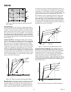
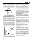
10 COMP RATIO SET Compression Ratio Set Pin. A resistor to ground from this pin sets the compression ratio as
shown in Figure 1. Figure 5 gives resistor values for various rotation points.
11 ROTATION SET Rotation Point Set Pin. This is set by a resistor to the positive supply. This resistor together
with the gain adjust pin determines the onset of limiting. A typical value for this resistor is
17K for a 100 mV “rotation point.” Increasing the resistor value reduces the level at which
limiting occurs. Refer to Figure 9.
12 POWER DOWN Power-Down Pin. Connect to ground for normal operation. Connect to positive supply for
power-down mode.
13 OUTPUT Output Signal.
14 V+ Positive Supply, +5 V Nominal.
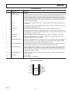
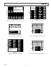
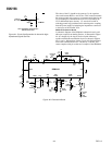
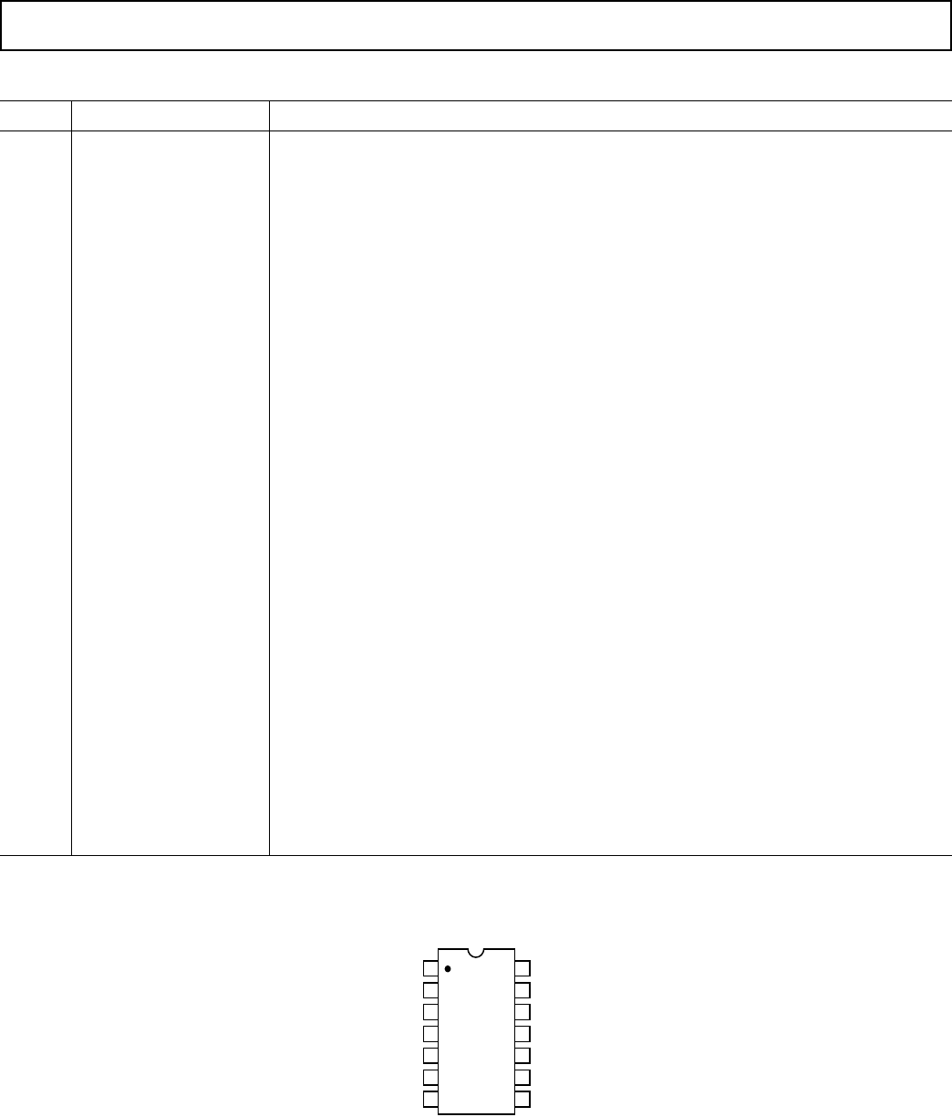
PIN CONFIGURATION
14
13
12
11
10
9
8
1
2
3
4
7
6
5
TOP VIEW
(Not to Scale)
GND
ROTATION SET
POWER DOWN
OUTPUT
V+
GAIN ADJUST
VCA
IN
VCA
R
SSM2166
AVG CAP
NOISE GATE SET
COMP RATIO SET
BUF OUT
–IN
AUDIO +IN