


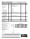
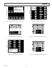

Parameter Symbol Conditions Min Typ Max Units
AUDIO SIGNAL PATH
Voltage Noise Density
e
n
15:1 Compression 17 nV/√Hz
Noise 20 kHz Bandwidth, V
IN
= GND –109 dBu
1
Total Harmonic Distortion THD+N 2nd and 3rd Harmonics, V
IN
= –20 dBu 0.25 0.5 %
22 kHz Low-Pass Filter
Input Impedance Z
IN
180 kΩ
Output Impedance Z
OUT
75 Ω
Load Drive Resistive 5 kΩ
Capacitive 2 nF
Buffer
Input Voltage Range 1% THD 1 V rms
Output Voltage Range 1% THD 1 V rms
VCA
Input Voltage Range 1% THD 1 V rms
Output Voltage Range 1% THD 1.4 V rms
Gain Bandwidth Product 1:1 Compression, VCA G = 60 dB 30 MHz
CONTROL SECTION
VCA Dynamic Gain Range 60 dB
VCA Fixed Gain Range –60 to +19 dB
Compression Ratio, Min 1:1
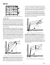
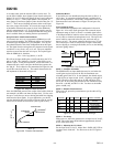
Compression Ratio, Max See Figure 5 for R
COMP
/R
ROT
15:1
Control Feedthrough 15:1 Compression, Rotation Point = –10 dBu ±5mV
POWER SUPPLY
Supply Voltage Range V
S
4.5 5.5 V
Supply Current I
SY
7.5 10 mA
Quiescent Output Voltage Level 2.2 V
Power Supply Rejection Ratio PSRR 50 dB
POWER DOWN
Supply Current Pin 12 = V+
2
10 100 µA
NOTES
1
0 dBu = 0.775 V rms.
2
Normal operation: Pin 12 = 0 V.
Specifications subject to change without notice.
REV. A
– 2 –
CAUTION
ESD (electrostatic discharge) sensitive device. Electrostatic charges as high as 4000 V readily
accumulate on the human body and test equipment and can discharge without detection.
Although the SSM2166 features proprietary ESD protection circuitry, permanent damage may
occur on devices subjected to high energy electrostatic discharges. Therefore, proper ESD
precautions are recommended to avoid performance degradation or loss of functionality.
SSM2166–SPECIFICATIONS
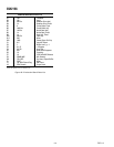
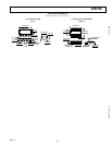
ORDERING GUIDE
Temperature Package Package
Model Range Description Option
SSM2166P –40°C to +85°C Plastic DIP N-14
SSM2166S –40°C to +85°C Narrow SOIC SO-14
ABSOLUTE MAXIMUM RATINGS
Supply Voltage . . . . . . . . . . . . . . . . . . . . . . . . . . . . . . . . .+10 V
Audio Input Voltage . . . . . . . . . . . . . . . . . . . . .Supply Voltage
Operating Temperature Range . . . . . . . . . . . . –40°C to +85°C
Storage Temperature Range . . . . . . . . . . . . . –65°C to +150°C
Junction Temperature (T
J
) . . . . . . . . . . . . . . . . . . . . . +150°C
Lead Temperature (Soldering, 60 sec) . . . . . . . . . . . . +300°C
ESD RATINGS
883 (Human Body) Model . . . . . . . . . . . . . . . . . . . . . . 2.0 kV
THERMAL CHARACTERISTICS
Thermal Resistance
14-Lead Plastic DIP
θ
JA
. . . . . . . . . . . . . . . . . . . . . . . . . . . . . . . . . . . . 83°C/W
θ
JC
. . . . . . . . . . . . . . . . . . . . . . . . . . . . . . . . . . . . 39°C/W
14-Lead SOIC
θ
JA
. . . . . . . . . . . . . . . . . . . . . . . . . . . . . . . . . . . 120°C/W
θ
JC
. . . . . . . . . . . . . . . . . . . . . . . . . . . . . . . . . . . . 36°C/W
(V+ = +5 V, f = 1 kHz, R
L
= 100 kΩ, R
GATE
= 600 kΩ, R
ROTATION
= 3 kΩ, R
COMP
= 0 Ω,
R1 = 0 Ω, R2
= ∞⍀, T
A
= +25؇C, unless otherwise noted, V
IN
= 300 mV rms.)
WARNING!
ESD SENSITIVE DEVICE