


SSM2166
REV. A
–12–
or an audio cable, then the onboard OP113 can be used. To
use the OP113 buffer, insert Jumper J4 into board socket pins
labeled “4” and “5” and insert Jumper J5 into board socket pins
labeled “6” and “7.” If the output buffer is not required, re-
move Jumper J5 and insert Jumper J4 into board socket pins “5”
and “7.” There are no blocking capacitors either on the input
nor at the output of the buffer. As a result, the output dc level
of the buffer will match the output dc level of the SSM2166,
which is approximately 2.3 V. A dc blocking capacitor may be
inserted on Pins 6 and 7. An evaluation board and setup proce-
dure is available from your Analog Devices representative.
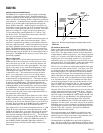
Setup Procedure with Evaluation Board
To illustrate how easy it is to program the SSM2166, we will
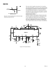
take a practical example. The SSM2166 will be used interface
an electret-type microphone to a post-amplifier. You can use
the evaluation board or the circuit configuration shown in Figure
22. The signal from the microphone was measured under actual
conditions to vary from 1 mV to 15 mV. The post-amplifier
requires no more than 500 mV at its input. The required gain
from the SSM2166 is, therefore:
G
TOT
= 20 × log (500/15) = 30 dB
We will set the input buffer gain to 20 dB and adjust the VCA
gain to 10 dB. The limiting or “rotation” point will be set at
500 mV output. From prior experience, we will start with a 2:1
compression ratio, and a noise gate threshold that operates be-
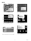
low 100 µV. These objectives are summarized in Figure 24, and
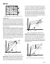
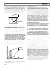
we will fine-tune them later on. The transfer characteristic we
will implement is illustrated in Figure 25.
INPUT RANGE
OUTPUT RANGE
LIMITING LEVEL
COMPRESSION
BUFFER GAIN
VCA GAIN
NOISE GATE
1-15 mV
TO 500 mV
500 mV
2:1
20 dB
10 dB
100 V
Figure 24. Objective Specifications
Note: the SSM2166 processes the output of the buffer, which in
our example is 20 dB or ten times the input level. Use the oscil-
loscope to verify that you are not driving the buffer into clipping
with excessive input signals. In your application, you should
take the minimum gain in the buffer consistent with the average
source level as well as the crest factor (ratio of peak to rms).
INPUT – mV
500
40
0.1 101.0
OUTPUT – mV
15
ROTATION POINT
COMPRESSION
REGION
1
2
LIMITING REGION
GATE THRESHOLD
Figure 25. Transfer Characteristic
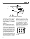
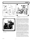
Evaluation Board
If you build your own breadboard, keep the leads to Pins 3, 4,
and 5 short. A convenient evaluation board is available from
your sales representative. The R and C designations refer to the
demonstration board schematic of Figure 22 and parts list,
Figure 28.
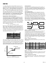
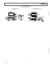
Test Equipment Setup
The recommended equipment and configuration is shown in
Figure 26. A low noise audio generator with a smooth output
adjustment range of 50 µV to 50 mV is a suitable signal source.
A 40 dB pad would be useful to reduce the level of most genera-
tors by 100× to simulate the microphone levels. The input volt-
meter could be connected before the pad, and need only go
down to 10 mV. The output voltmeter should go up to 2 volts.
The oscilloscope is used to verify that the output is sinusoidal,
that no clipping is occurring in the buffer, and to set the limiting
and noise gating “knees.”
AC
VOLTMETER
SIGNAL
GENERATOR
SSM2166
EVALUATION
BOARD
AC
VOLTMETER
OSCILLOSCOPE
Figure 26. Test Equipment Setup
STEP 1. Configure the Buffer
The SSM2166 has an input buffer that may be used when the
overall gain required exceeds 20 dB, the maximum user-
selectable gain of the VCA. In our example, the desired output
is 500 mV for an input around 15 mV, requiring a total gain of
30 dB. We will set the buffer gain at 20 dB, and adjust VCA
for 10 dB. In the socket pins provided on the evaluation board,
Insert R1 = 100 kΩ, and R2 = 11 kΩ. You have set the buffer
gain to 20 dB (×10).
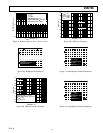
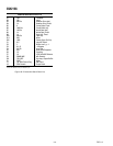
STEP 2. Initialize Potentiometers
With power off, preset the potentiometers per the table of Fig-
ure 27 below.
GAIN ADJUST
(VCA)
FUNCTION
ROTATION
POINT
COMPRESSION
RATIO
NOISE GATE
ZERO
ZERO
ZERO
1 M⍀
INITIAL
RESISTANCE
INITIAL
POSITION
CCW
CCW
CCW
CW
RANGE
0–20 k⍀
0–50 k⍀
0–100
k⍀
0–1 M⍀
POT
R10
R3
R6
R7
0 dB; CW TO INCREASE
VCA GAIN
1 V; CW TO REDUCE
ROTATION POINT
1:1; CW TO INCREASE
COMPRESSION
300 V; CCW TO
INCREASE THRESHOLD
EFFECT OF CHANGE
Figure 27. Initial Potentiometer Settings
STEP 3. Test Setup
With power on, adjust the generator for an input level of 15 mV,
1 kHz. The output meter should indicate approximately 100 mV.
If not, check your setup.
STEP 4. Adjusting the VCA Gain
Set the input level to 15 mV. Adjust R10—GAIN ADJ CW for
an output level of 500 mV. You have now set the VCA gain to
10 dB.